Week 7 State of charge estimation
State of Charge Estimation
Question :
1.Simulate the 3 test cases from harness dashboard and write a detailed report on the results
2.What is coulomb counting? Refer to the above model and explain how BMS implements coulomb counting for SOC estimation?
Aim :
Simulate the 3 test cases from harness dashboard and understand the result. Understand the concept of coulomb counting for SOC estimation.
Objective :
- Simulate the 3 test cases from harness dashboard
- Understand the concept of coulomb counting for SOC estimation.
Download link of BMS Model : https://in.mathworks.com/matlabcentral/fileexchange/72865-design-and-test-lithium-ion-battery-management-algorithms?s_tid=srchtitle
Steps to simulate BMS model:
- Download zip file and extract it.
- Open MATLAB-Simulink. Clock on open and select BMS closed loop model.
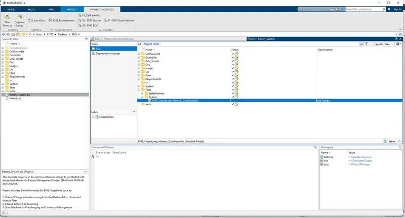
- Click on Battery_System.prj and make sure all the files have grin tick indicating that BMS model is ready to start.
- After opening BMS system go for harness dashboard.
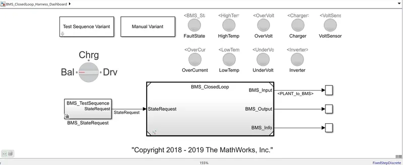
Harness dashboard:
This is a simulated environment where we create 3 test cases and load the battery pack according to the drive cycle given by test cases. We create test specific environment for testing specific model. We perform closed loop testing by creating physical plant model and we test the potential of the model. We can use test harnesses which offer management and synchronization capabilities.
Initially when no test is conducted, we can see below harness board.
Case 1:
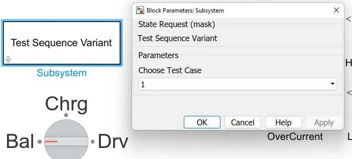
click on the Test Sequence Variant Subsystem and choose the Test case as 1 and run the model using RUN command
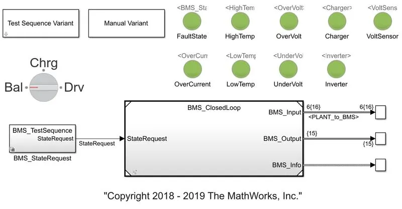
Here we see all green signals means there is no fault or error in this model.
We get following chart as result of case1
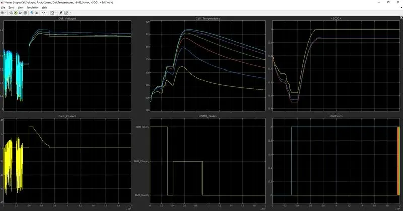
In the result scope we can see following parameters
- Cell voltages
- cell temperatures
- SOC
- Peak current
- BMS state
- Balancing of the cells i.e BalCmd
From 0 to 0.3 *10^4 secs
- BMS driving mode is in BMS driving mode.
- Cell voltages are varying from 3.2 v to 3.9 v.
- pack currents are fluctuating from 20 A to -60 A.
- cell temperatures are rises up to 300k temperature.
- SOC is reduced to 80% to 30% of the battery
- Balancing of all cells are balanced i.e; zero
From 0.3 *10^4 to 0.4 * 10^4 secs
- BMS driving mode is in BMS standby mode.
- Cell voltages are stable at 3.7 v.
- pack currents are stable at 0 A.
- cell temperatures are reduced slightly .
- SOC of the battery is contant. (No movement of the vehicle)
- Balancing of all cells are balanced i.e; zero except cell 6 is unbalanced.
From 0.4 *10^4 to 0.9 * 10^4 secs
- BMS driving mode is in BMS charging mode.
- Cell voltages are rises to 4.2 v.
- pack currents are suddenly rises to 30 A and then decreases slightly.
- cell temperatures are rises up to 315 k approximately .temperature and redues slightly.
- SOC of the all cells are rised to 100 % soc its capacity but cell 1 is 100% soc and cell 2 &3 are ~90% soc
- while charging constant current and constant voltage charging modes are done, During constant current 0.4 to 0.5 secs soc is rises fastly but during constant voltage 0.5 to 0.9 soc is slightly rises.
- Balancing of all cells are balanced i.e; zero except cell 6 is unbalanced.
Case 2: Change the test sequence variant to 2 and run model
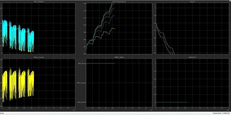
- Cell voltages are varying from 3.2 v to 3.9 v having four fluctuation zones.
- pack currents are fluctuating from 20 A to -60 A having four fluctuation zones.
- cell temperatures are rises up to 325k temperature.
- SOC is reduced to 80% to 0% of the battery with in 8700 secs
- Balancing of all cells are balanced i.e; zero
Case 3: Change the test sequence variant to 3 and run model
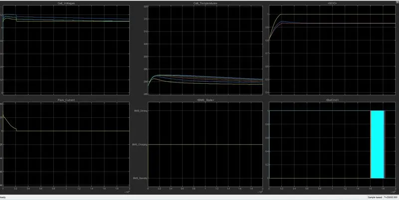
- BMS driving mode is in BMS Charging mode.
- Cell voltages are decreases from 4.2 v.
- pack currents are decreases from 20 A to 0 A.
- cell temperatures are rises up to ~292k temperature and then decrease slightly.
- SOC of the all cells are raised to 100 % soc its capacity but cell 1 is 100% soc and cell 2 &3 are ~90% soc
while charging constant current and constant voltage charging modes are done, During constant current 0 to 0.2 secs soc is rises sharply but during constant voltage 0.2 to 2 soc is slightly rises.
- Balancing of all cells are balanced i.e; zero except cell 6.
Coulomb Counting Method:
- It is a method used for estimating the state of charge (SOC) of a battery.
- The coulomb counting method is expedient for state-of-charge (SOC) estimation of lithium-ion batteries with high charging and discharging efficiencies. The charging and discharging characteristics are investigated and reveal that the coulomb counting method is convenient and accurate for estimating the SOC of lithium-ion batteries. The Coulomb counting method measures the discharging current of a battery and integrates the discharging current over time in order to estimate SOC.
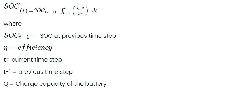
- In this method, SOC is taken at the previous time step SOC(t-1) and the amount of energy removed/added at the current time step is subtracted/added from the SOC of the previous time step SOC(t-1) to obtain the amount of energy present in the battery at the present instant.
The SOC estimation in the coulomb counting method is done using the below equation
BMS implementation of coulomb counting for SOC estimation
To compute SOC using Coulomb counting method open BMS_closedloop model
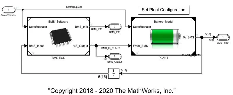
Click on the BMS ECU subsystem, following block diagram opens.
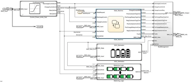
Now by clicking on SOC Estimation subsystem and following block diagram opens.
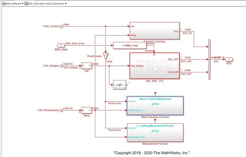
To calculate SOC by coulomb counting method open Coulomb subsystem block and following subsytem opens.
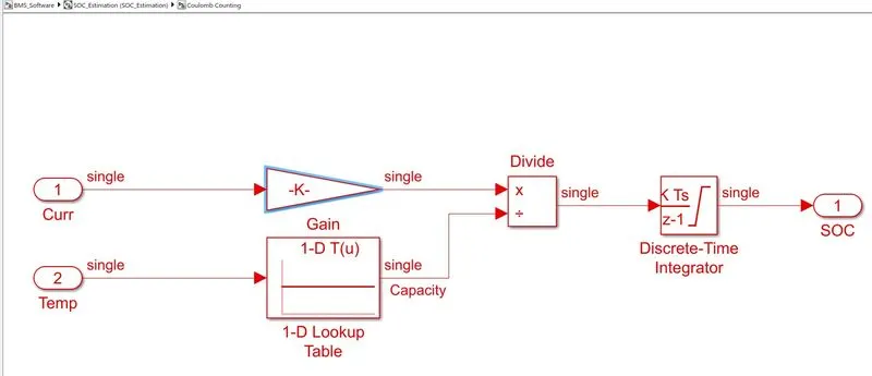
In coulomb counting block
- Accepts two input signals: current and temperature, with the current signal going to the gain block and the temperature signal going to the battery time and current lookup tables.
- Both blocks are linked to the split block, and these signals are sent to discrete-time integrator to track the charge, which then aids in the calculation of the state of charge.
- The positives of this is its simplicity and cheap capital cost, while the disadvantages include a buildup of current sensor error and its inability to recover from the erroneous start condition. due to a lack of voltage measurement feedback.
- Opening the coulomb counting method we get to see the gain, 1-D look Up table, Product and Discrete Time Integrator block
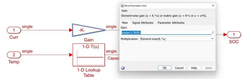
The discharge current from the battery given to a gain having value of 1/3600 to convert A to Ah.
Now open parameters of Discrete time integrator.
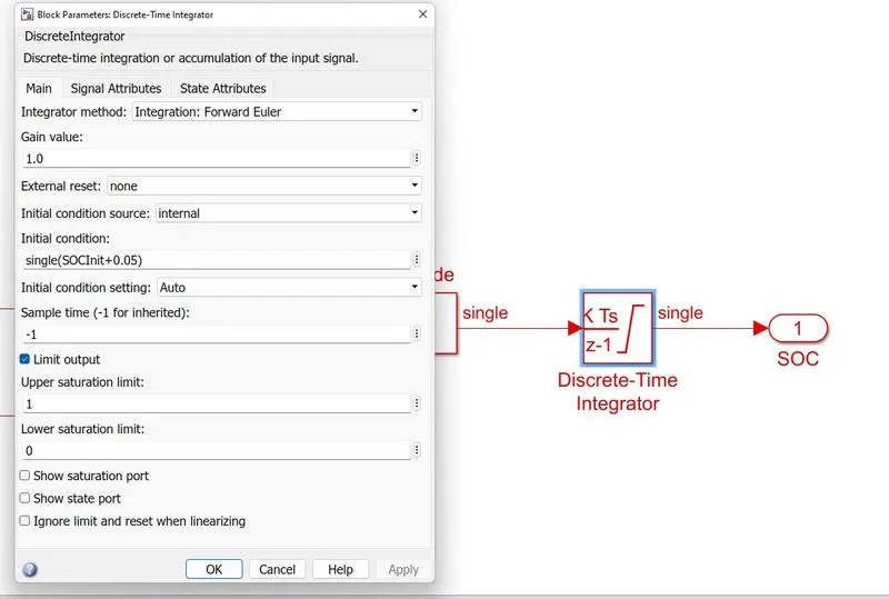
- Current is divided by the capacity due to temperature change and then integrated with the gain value of -1 with sample time of -1 as discrete type integrator is used here.
- The saturation limits are given which are 1 to 0. So that we get SOC value from 0 to 1 multiplied with 100 to get percentage of SOC.
- Coulomb Counting methos is simple and it require less computational compared to other two methods.
Coulomb counting method is nothing but the integration of current over the period of time.
The Drawbacks of this method are accumulation of current sensor error and inability to recovery from wrong initial condition because of lack of feedback from voltage measurement, and how SOC is measured in this method.
References:
- https://www.proquest.com/docview/2535459724
- https://www.amrita.edu/publication/soc-estimation-of-lithium-ion-battery-using-combined-coulomb-counting-and-fuzzy-logic-method/
- https://www.ijert.org/research/integration-of-coulomb-counting-method-in-battery-management-system-for-electric-vehicle-IJERTV9IS050639.pdf