Week 7 State of charge estimation
AIM:Study the Behaviour and Simulate the Design and Test of Lithium Ion Battery Management Algorithms
Objective:
1.Simulate the 3 test cases from harness dashboard and write a detailed report on the results
2.What is coulomb counting? Refer to the above model and explain how BMS implements coulomb counting for SOC estimation ?
INTRODUCTION
THEORY:
Battery Mannagement System
Lithium-ion battery packs are the predominant energy storage systems in aircraft, electric vehicles, portable devices, and other equipment requiring a reliable, high-energy-density, low-weight power source. The battery management system (BMS) is responsible for safe operation, performance, and battery life under diverse charge-discharge and environmental conditions. When designing a BMS, engineers develop feedback and supervisory control that:
- Monitors cell voltage and temperature
- Estimates state-of-charge and state-of-health
- Limits power input and output for thermal and overcharge protection
- Controls the charging profile
- Balances the state-of-charge of individual cells
- Isolates the battery pack from the load when necessary
Design and simulate the battery management systems by:
- Modeling Battery packs using electrical networks whose topology mirrors that of the actual system and scales with the number of cells
- Parameterizing equivalent circuit elements using test data for accurate representation of cell chemistry
- Designing the Power electronic circuit that connects the pack with the controls
- Developing closed-loop control algorithms for supervisory and fault detection logic
- Designing state observers for state-of-charge and state-of-health online estimation
SIMULINK MODEL :
The Main Components of BMS are
We can use this model for test up simulation where we can for ex using repetative cycle for different environmental condition to evalute the system response to potential unsafe condition like temperature ,voltage current outside the recommended limits.
THe Battery & BMS is in BMS Closed Loop
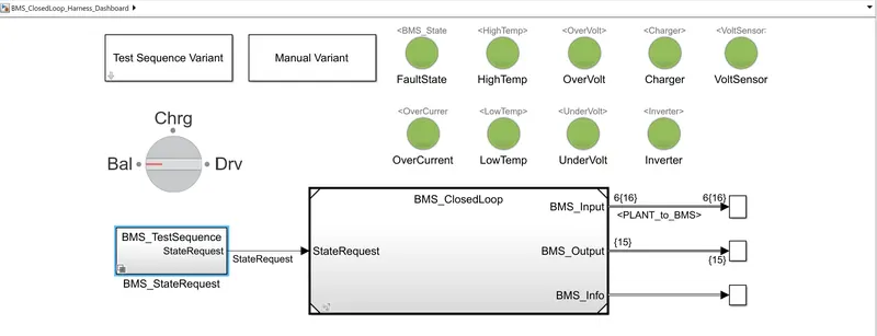
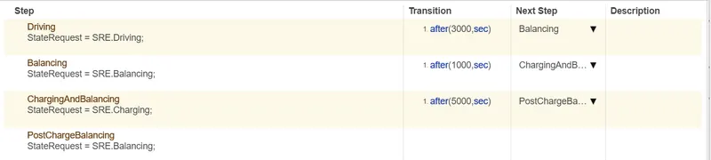
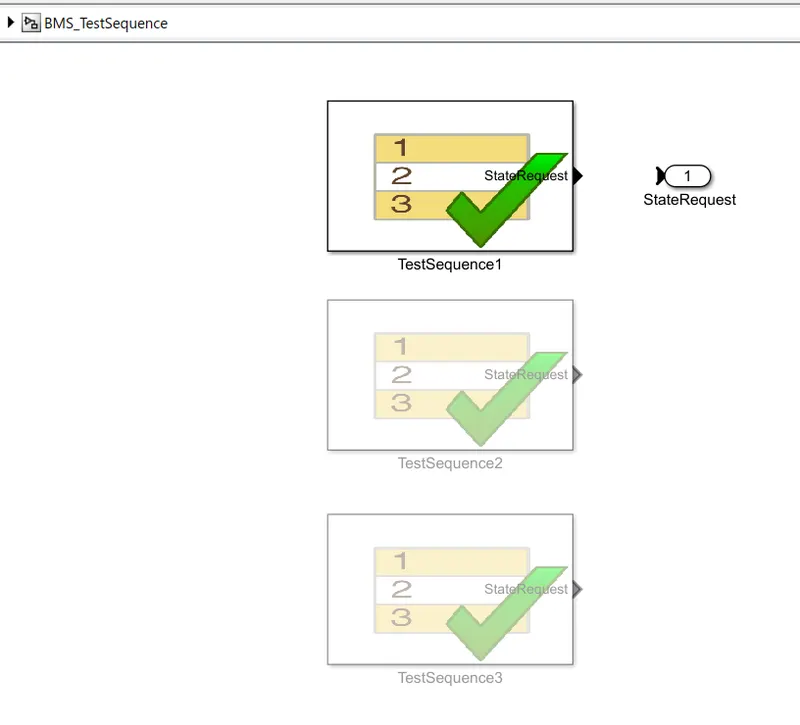
The Test Sequence Variant Consists of Different Driving Senario Provided by the Subsystem of BMS Test sequence State request
The green light indicates wether there is been a fault, for example any cell has reached overtemperature condition.
The system itself has a model representing BMS ECU with Monitoring and control algorithm connected to a block Plant
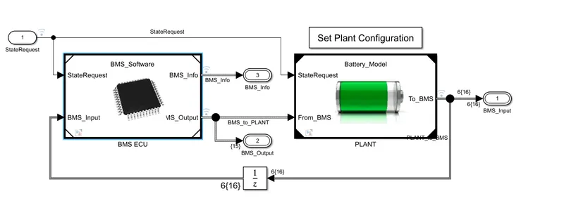
This Model contains 2 version of the battery pack
1.Six cell connected in series
2.larger one with 16 Module each Module contains 6 cell
6 Cell connected in series
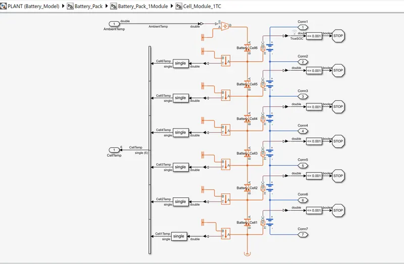
This Battery pack is Modeled in simscape the component color tells the significance domain.The blue color indicates the electrical and orange color indicates the Thermal.The Thermal layer is Asymmetrical with cell 6 insulated on one side no heat can desipiate in the direction and cell 1 exposes to the outside atmosphere these getting rid of heat by convection.
The set of charger and Inverter Contactor Circuitary
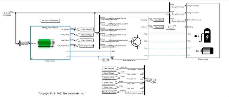
Charger and Load represent current source to follow the charging and driving performance from the source block at Model Top level
State Machine
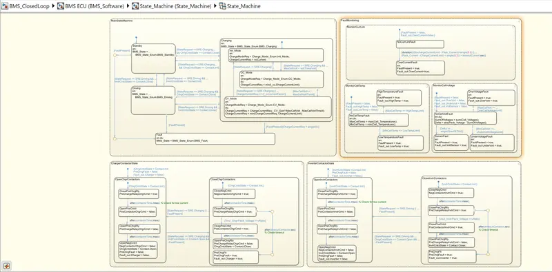
State Machine defines the main operating state of BMS.It is represented using state flow in State flow the components represent the State.
These are active and inactive depending upon the the condition. inside the state the code that executes the ntry, During or Exit from the state.This state Machine has 4 parallel state.Parallel here meaning that they can be active at same time.
1.Difine the variable BMS state which indicates
1.Standby
2.Driving
3.Charging
4.Fault
Charging comprises Constant current and Constant voltage Stages
2.The second state switches the fault state ON in case the current voltage or temperature value reaches an unsafe level.
The 3rd and 4th sates define the contactor ON and OFF sequence for charger and inverter this is needed for excessive current inrush at the beginng of the charger stage.
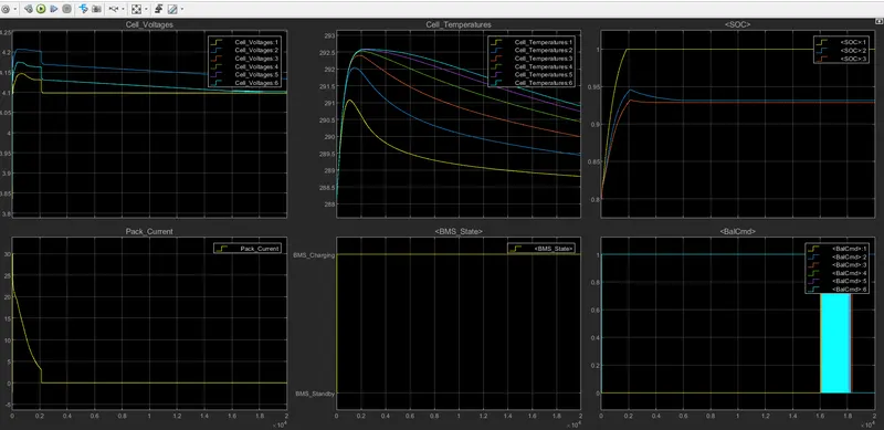
TEST RESULTS:The Scope shows the result for the Test Case 1
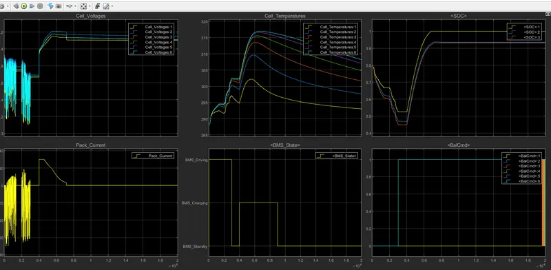
- From the results We can observe in the Driving,Balancing, charging,sequencing operation we first observe the individual voltage changing as a result of current flowing in and out at begning of simulation there is slightly SOC imbalance.The value conversion one another as it produces balancing of SOC.
- During constant current stage the current is deviatedThe maximum Module cell is high enoungh compared to prescribed 4.4v limit on excessive high current would flow through the voltage behyond the threshold.significantly limiting the life of the battery.
- The cell temperature significantly shows the temperature of hottest and clodest cell. the reason is mainly Asymmetric in Module layer in terms of thermal behaviour. the cell no 6 gets significantly hotter then the cell no 1because thermal insulated on one side.The temperature will cause much faster degradation of cell 6 compared to cell 1.hence the active thermal management required to maintain thermal diffrance of few degree celcius.
- SOC of the same battery cell each formed with differnt methods
- From graph we can see yellow color represents the columb counting in graph SOC
- the orange represnts the UKF
- The Blue represnents the EKF
- The initial SOC in simulation is 75% but SOC estimated to be 80% to Ecess their Capacity to recover.
SECOND TEST CASE
For this We go to the Test Sequence Variant and select the test case 2 . then to run the simulation for the given time.the result shows that there is a fault condition in the vehicle. the dashboard on the model depicts the same with red colour indication.
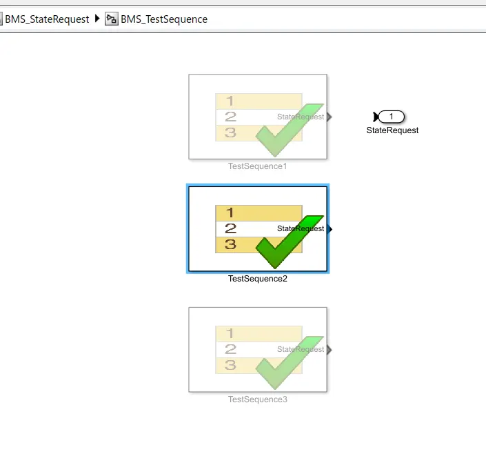
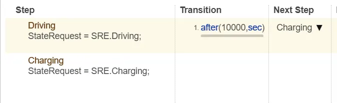
This test case has two phases for the battery pack .I.e driving and charging
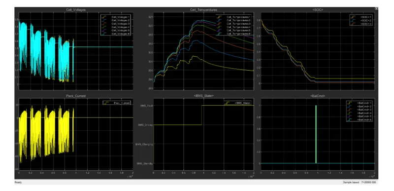
The scope shows the various parameter for the BMS model under second test case.After 10,000 sec when the driving cycle is over the fault condition occurs and so the SOC does not increase even fo the charging phase
The last test is third test sequence
For this test we have to select the Test Sequence and select the test case 3.
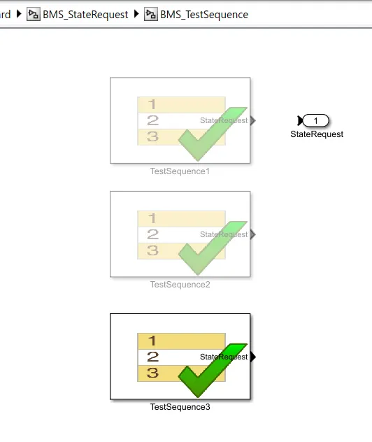
There is only only one single phase here for the third test case .i.e Charging phase.

The Scope shows the result for the third test case.Here the SOC incresaes from 80% to 100% and then remins in standby mode.
2.What is coulomb counting? Refer to the above model and explain how BMS implements coulomb counting for SOC estimation ?
The columb counting method measures the discharging current of a battery and integrates the discharging current over the time in order toestimate the SOC.Columb counting method is done to estimate the,which is estimated from discharging current and previously estimated SOC values,SOC is calculated by the following Equation
`SOC(t)=SOC(t-1)+(I(t))/Q_n*Deltat`
From the above model the SOC is estimated with three Methods
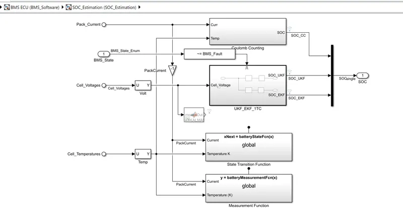
1.Columb Counting Consists of intergating the current that enters and leave the cell to keep track of safe charge over time.Benifit of this method is its simplicity & very low computational cost.Its draw include the accumulation of crrent sensor error and its inability to recover from intial condition because of lack of feedback from voltage measurement.
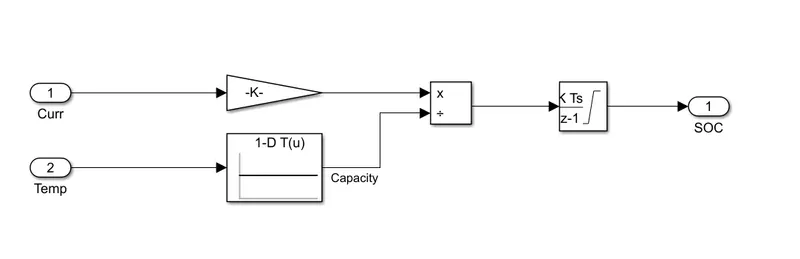
Here the Soc is estimated for the accurate and the Unsented & extended Kalman Filter is used to estimate the SOC and is based on the system of severity is non linearity.In this case only non linearity present is given by the OCV and SOC relationship and it is mild one it is expected that EKF should give accurate Estimation.
Kalman Filter has 2 parts 1.State update it preditcs the current state based on the previous state value and inpuut.
2.Measurement update corrects the prediction using newly required data.
CONCLUSION: the Behaviour and Simulation, the Design and Test of Lithium Ion Battery Management Algorithms is studied and the Test for the three test sequence is compared.