Week 7 State of charge estimation
The matlab project model that has been developed to simulate the different characteristics of the BMS along with the Battery modelling is been developed by matlab and Now here we are gonna understand the different behaviour of the Battery Pack along with BMS in the different cases like Charging, Discharging and Balancing.
BMS closed loop Harness Dashboad-
The link given in the Challenge itself will provide the model file named BMS_ClosedLoop_Harness_Dashboard.slx and here is the first view of the model where we see different indicators that are the output of the BMS and gives idea about The current state of the Battery pack. and we can see The input block name BMS_StateRequest which implies the different state request given to the closed loop model, There are 2 different ways to give input command that is manual varient and the Test sequence. The output of the model is mainly related to BMS and it is observed in scope to analyse the performance of the BMS system.
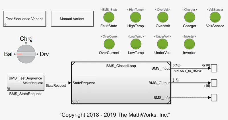
[1] 3 test cases from harness dashboard
here in this project report we're simulating 3 different cases that is inbuilt in the model to check the performance and the bahviour of the model in this three different cases. There are two cases which content Charging and discharging State request and the other case content the combination of these cases.
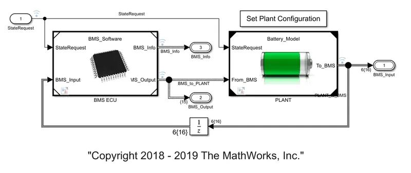
The above figure gives first idea about the closed loop BMS system that is Basically controlling the input and output of the Battery pack and gives information of the current state of the Battery pack. Now take a look at the BMS ECU block.
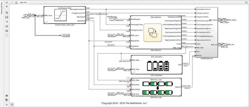
Here we can see the first block is for calculating the curent and voltage limits so that other features of the BMS can use this values in order to control the Battery pack. now this output is given to the state machine, which is nothing but the matlab chart model to implement the BMS logic with the state changes. There is another block named SOC_Estimation that contains Three different method to calculate the SOC of the Battery i.e. colomb counting, kalman filter and extended kalman filter.
There are another block named Balancing logic Which implement the create balancing command in order to match the voltage differnce between different cells in the given range. at the last there is Bus management block which combine different output signals of the BMS and give either Battery pack or the user itself.
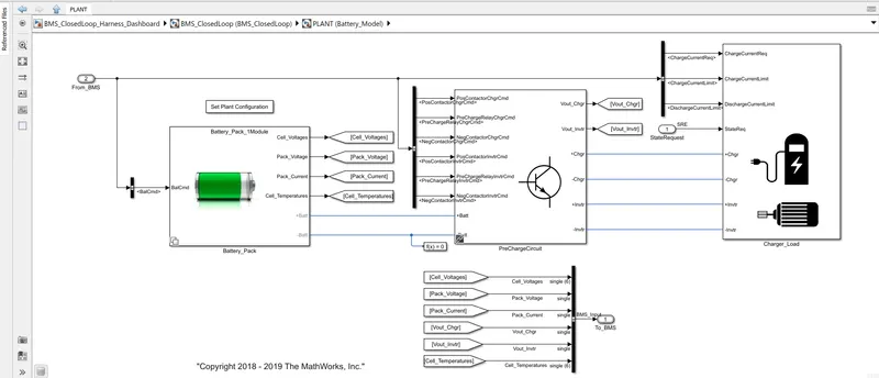
The Battery PLANT model has battery pack model and precharge circuit consist of two circuit of series connected resistor for charging and load contacts, further the charge load block contains charging and motoring load logic. The chrging logic supplies the current according to the current request from the BMS and the load circuit will draw current according to a driving cycle which has a repeating sequence characteriestics and the information regarding this plant is given back to the BMS ECU block.
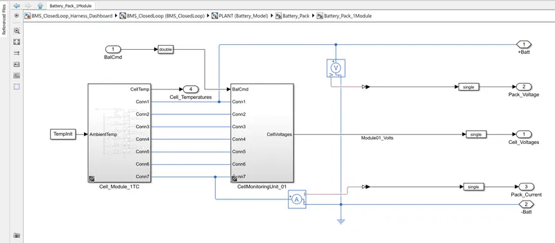
in the Battery pack subsystem there is a single module and a 16 module model is available. for simplicity we use single module block that has a cell module block and a cell monitoring block. the cell module contains 6 cells connected in series, therefore 7 connecting ports, take a look at the cell module
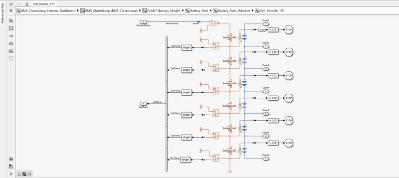
here we can see the 6 cells are connected in series that is an Table based battery model that has input temoerature port and output SOC port, the thermal port that is connected through ambient temperature with the convection heat transfer block according to the cell positioning in the battery pack and this cells have different temperature sensors, this sensors output will be analyzed later.
so the cell monitorng unit contains passive cell balancing circuit and the input to this controlled passive balancing circuit is given by the cell balancing block that we discussed in the BMS ECU.
THE FIRST CASE-
Now finally we discuss the first case so we choose
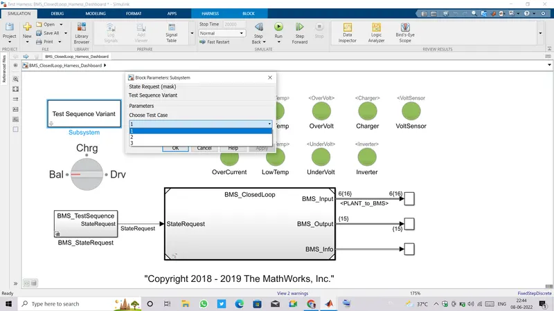
now we choose the test squence varient to test case 1 and run the simulation for the 20000 secs and obesrve the output which is shown below....
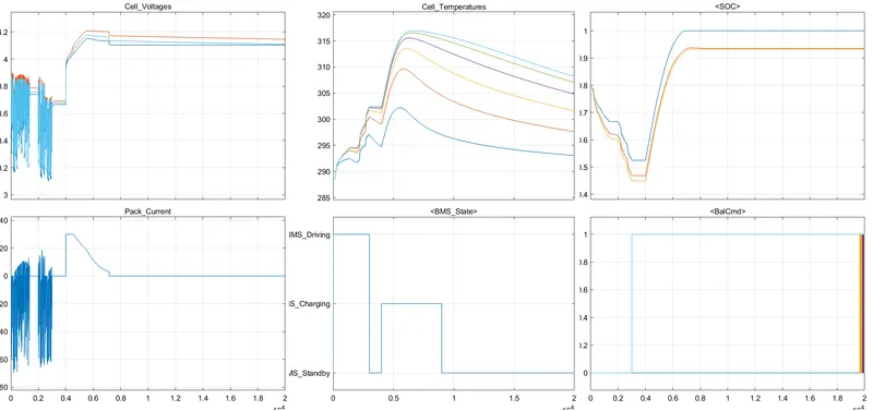
here we can see in the BMS state, for the first 2500 sec the model runs for driving the load and after 4000 secs the model runs in the charging mode then after 9000 secs the model runs in the BMS standby mode. so first we observe the cells voltages ie. all 6 of them are sharing the load and have same characterstics but due to different operating temerature the cell voltages are differ as they are connected in series therfore some cells are gonna discharge differntly even they have same discharging currents.
Now for first 2500 sec the state command to the closed loop BMS model is given as driving load so the Battery pack will drive the load according to the driving cycle therefore it has too much ripple in the load current as well as cells voltages and in this period the cell voltage is gonna rise from 288K and according to the placement of the ccells the temperature of different cells rises in the different manner. and SOC of the Battery pack is gonna decreases and the 3 different SOC's are from three different algorithm calculated externally from the battery pack. As soon as the discharging of the battery is done the standby mode is come and Balance command is gonna active for all five cells which has higher voltages and the passive Balancing circuit will be active in order to reduce all cells voltages to the cell voltage that has minimum voltage.
Then after 2500secs the battery state is changed into charging mode then Constant Current(CC) charging comes into picture and the charging current maintains to the upper charging current limit by varing the charging voltage according to the cell voltage and as cells charges the cell voltage rises which results in rising of charging voltage but as soon as the charging voltage reaches the max charging voltage the charging state will changed into Constant Voltage(CV) charging and the charging current will decreases as time progresses and reached to the min charging current limit that is 2.5A and charger is disconnected and BMS state changes to Standby mode. In this period the SOC of packwill increase upto the maximum values (different for different SOC estimation methods). and the cell temperature is also rises very quikly as charging currents are high and decreases as currents will decreases. the balancing command will be acive in this period as cells voltages is not in the specified deltaV range.
Now in the last case the standby mode, No charging or discharging of the battery so the cells temperature drops and Balancing circuit is in action in order to match all cells voltages to the minimum cell voltage. Pack current will be zero so the pack SOC will not change.
THE SECOND CASE-
Now we choose the second test case from the test sequence and run the model for exact same period of time as before and we observe the discharging process throughout the simulation.
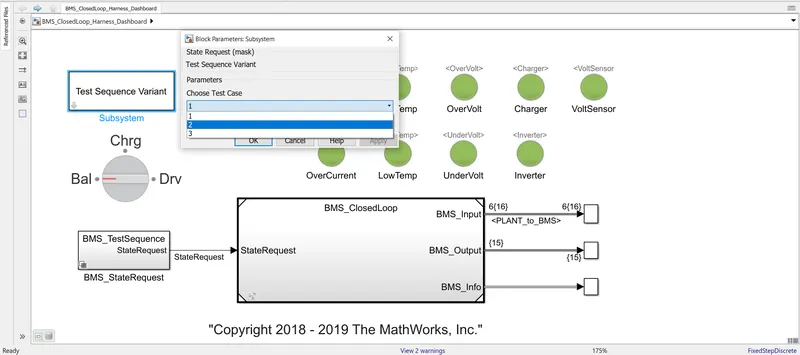
now we choose the test squence varient to test case 2 and run the simulation for the 20000 secs and obesrve the output which is shown below....
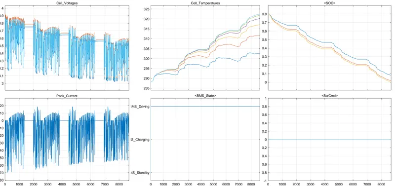
here we can see the driving cycle load is repeated in 4 times and model stops at 8692 seconds as the SOC of the pack reaches to zero and battery is disconnected so in this 8692 secs the discharge current followa load drive cycle current as well as cells voltages are also varry accordingly and the whole process is under the BMS driving state and temperaure of cells are continuesly increases as discharge happening in sequence some of the cell voltages will hit 323K and SOC of the battery pack will decreases with the discharging current and also temperature algorithm. the balancing command remains zero as discharging happening through out the simulation.
THE THIRD CASE-
Now we run the model for the third case that is the 3rd test sequence basically a charging case where whole time is given for the charging of the cell,
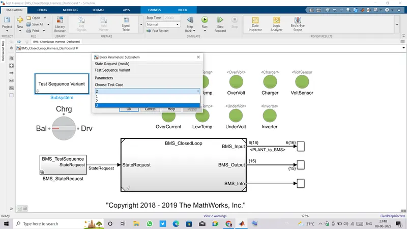
In the third case we run the model for 20000 secs and observe the output of the model which is shown in below,
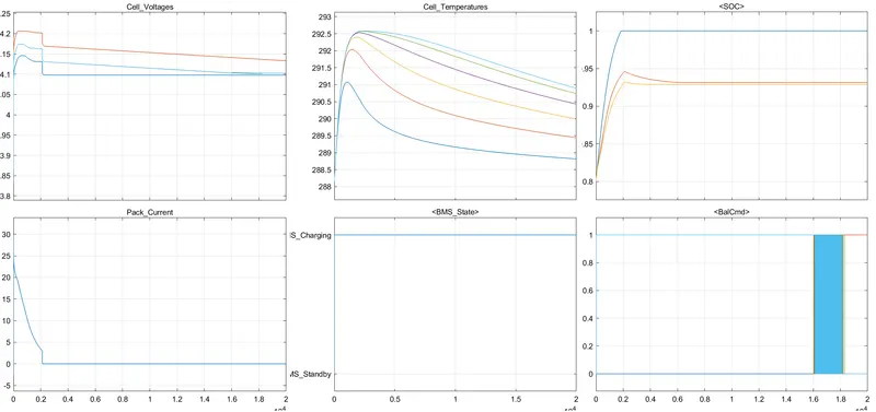
here we can see the BMS command is always at the charging mode thorughout the simulation, and we observe the initial SOC is 0.8(80%) which will increases instantaneously as the charging current comes into place and as soon as we connect the battery with the precharge circuit the charging current rises and will be at CC mode for a little time or no time as charging voltages reaches the max value due to the intial voltage of battery is high. so the charging is done mainly in the CV mode therefore the SOC rises and also cells temperature rises according to its position in the battery pack and environment. then temperature reduces as charging current decreases and charger is disconnected as charging current reaches min charging curreent(2.5A) and after charger disconnected the Battery pack SOC with colomb counting, kelman and extended kelmon filter are 1, 0.945 and 0.93 respectively. the uncented kalman filters SOC and extended kalman filter's SOCwill be reaches to a steady state value of 0.931 and 0.929 respectively.
As the BMS is in charging mode the cell balancing is active and it tries to match all cell voltages to a common value, after 18550 secs the cell voltages of the five cells are in the limits and only one cell will be at balancing condition ie. the orange one as this has highest voltage when the battery charges. but after the sufficient time period all cell voltages are settle within the limits or the same voltages.
[2] Coulomb Counting-
Coulomb counting is nothing but the integration of the current through the time that gives the charge supplied by the battery, and it can be refer for the SOC calculation of the Battery pack. As we know a battery can supply a limited amount of energy as it is not an infinite source of energy so the charge supply limited to the cell capacity also known as the 'Ah capacity' of the cell.
The basic idea about coulomb counting can be understand by following expression,
`I=(dQ)/(dt)` Amps
`dQ=I*dt`
`intdQ=intI*dt` Amp-sec
`Q=int(I*dt)/3600` Amp-hour
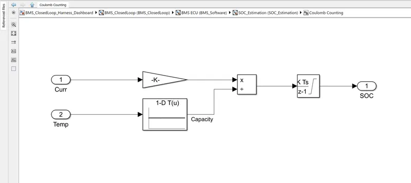
Now we open the model in the BMS_CLosedLoop_Harness_Dashboard and go to the BMS closed loop inside it a BMS ECU subsystem and inside it there is SOC_Estimation block where we can find the Coulomb counting block. In this model we can see the Coulomb counting model is taking Battery pack current and Temperature of the cells which is selected by a selector block. so the idea behind taking the temperature is that 'Temperature affect the Capacity of the Battery' therefore we take a lookup table to estimate the total capacity of the battery according to the operating temperature and it can be found in the datasheet of battery.
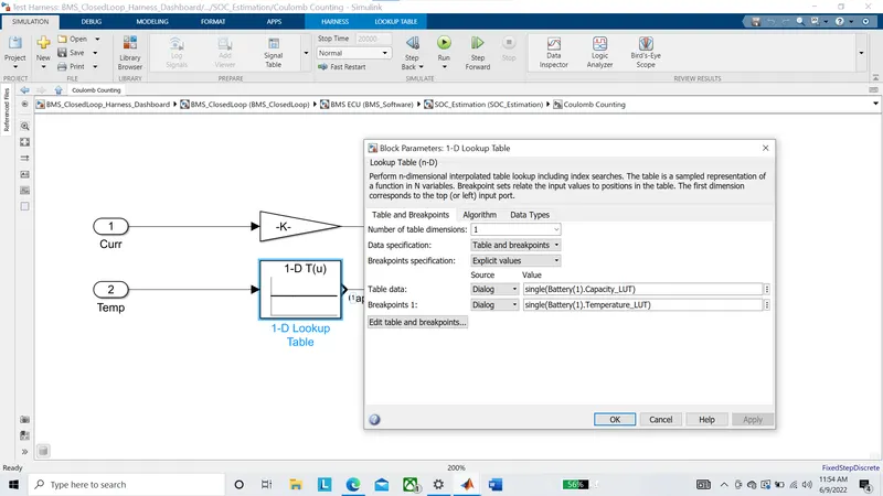
here we can see the table data is the battery capacity and the Breakpoints are the temperature values of the battery. so the question is why we need to take Battery capacity temperature? the answer to this question is, because the SOC is the ratio of the charge supplied by the battery to the battery capacity.
so we divide the previously calculated real time Ah-capacity to the total capacity of the Battery pack and use a discrete integrator block as the data used in this simulation are discrete. this model can also be realised with the continous system that will give more accurate SOC of the battery pack. The integrator block can be placed anywhere in the model as integration is an linear operator.