Week 7 State of charge estimation
State of charge estimation
AIM
- Simulate 3 test cases from the Harness dashboard of the project 'Lithium-Ion Battery Management Algorithms Design and Test'
THEORY
BMS - Battery Management System
- Li-ion battery, one of the common batteries that use in an electric vehicle are costly and prone to damages. The life span of the battery is important!!
- A battery-management system (BMS) is an electronic system or circuit that monitors the charging, discharging, temperature, and other factors influencing the state of a battery or battery pack. It’s used to monitor and maintain the health and capacity of a battery.
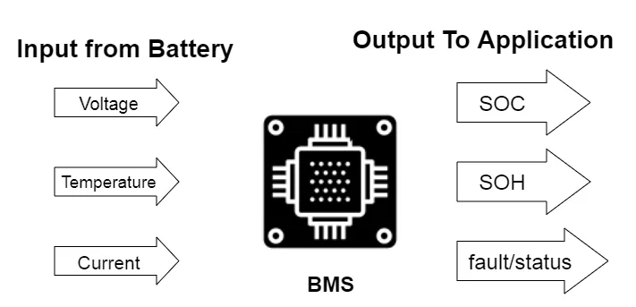
When designing a BMS, engineers develop feedback and supervisory control that:
- Monitors cell voltage and temperature
- Estimates state-of-charge and state-of-health
- Limits power input and output for thermal and overcharge protection
- Controls the charging profile
- Balances the state-of-charge of individual cells
- Isolates the battery pack from the load when necessary
- Simulink modelling and simulation capabilities enable BMS development, including single-cell-equivalent circuit formulation and parameterization, electronic circuit design, control logic, automatic code generation, and verification and validation.
With Simulink, engineers can design and simulate the battery management systems by:
- Modelling battery packs using electrical networks whose topology mirrors that of the actual system and scales with the number of cells
- Parameterizing equivalent circuit elements using test data for accurate representation of cell chemistry
- Designing the power electronics circuit that connects the pack with the controls
- Developing closed-loop control algorithms for supervisory and fault detection logic
- Designing state observers for state-of-charge and state-of-health online estimation
Using Simulink, engineers can exercise the battery management system over a range of operating and fault conditions before committing to hardware testing.
MODEL
Project 'Lithium-Ion Battery Management Algorithms Design and Test'
- The project uses Simulink to simulate the dynamic nature of a single battery cell and to scale your models to perform a system level simulation of the entire battery pack. Use these dynamic models of the battery pack to design and test algorithms for the battery management system.
- Battery Cell Characterization
- Detailed Battery Pack Plant Model
- Designing BMS Algorithms
- Code Generation
- Verification & Validation (Requirements + Test Cases)
- Hardware-In-Loop Testing of BMS
- The BMS model consists of a BMS ECU (electrical control unit) and a plant. The control unit with its various monitoring and control algorithms is connected to a block with the representation of the battery pack and associated circuitry and peripherals. This model contains two versions of the battery pack: a small one with just 6 cell series, and a larger 16-module pack, each module containing a 6-cell series string. The architecture is 6s-1p and 96s-1p packs, respectively.
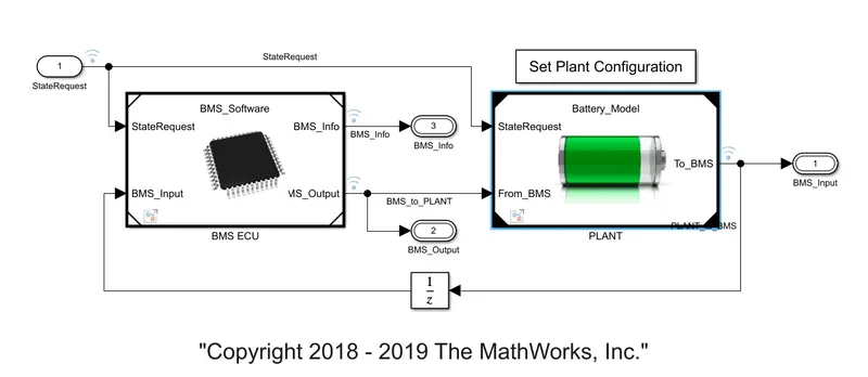
BMS ECU - Subblock:
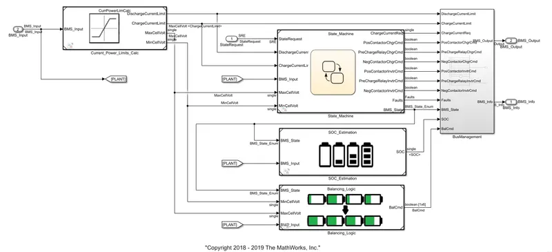
- The BMS ECU block includes the BMS state machine, the SOC estimation block, and the cell balancing block. This block Also determines the current power limit of the cells.
- State Machine defines the main operating state of the BMS. The state machine has four parallel states (parallel meaning that they can be active at the same time):
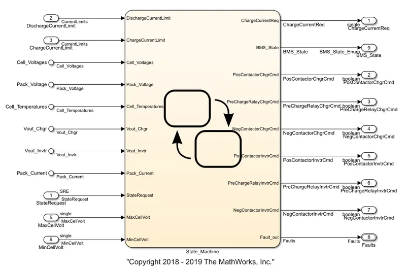
- The first one defines the variable BMS_State which indicates standby, driving, charging, and fault. Charging comprises constant current and constant voltage stages.
- The second state switches the fault state ON in case a current, voltage, or temperature value reaches an unsafe level.
- The third and fourth states define the contactor ON and OFF switching sequence for the charger and inverter. This is needed to avoid an excessively large current inrush at the beginning of the charging stage.
Battery Pack - PLANT Subblock
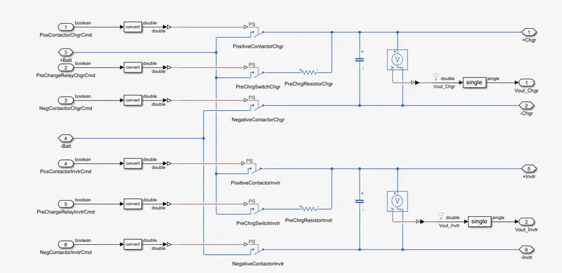
- This model includes two variants of Battery Pack (1. One module with 6 cells in series, 2. 16 modules with 96 cells in total). Battery Pack is connected to Charger / Load via Precharge Circuit and contactors. Precharge circuit is required ensure there is no sudden rush of current in/out of battery pack when connected to Charger or Load with large voltage difference. Closing or opening precharge contactors is done by BMS.
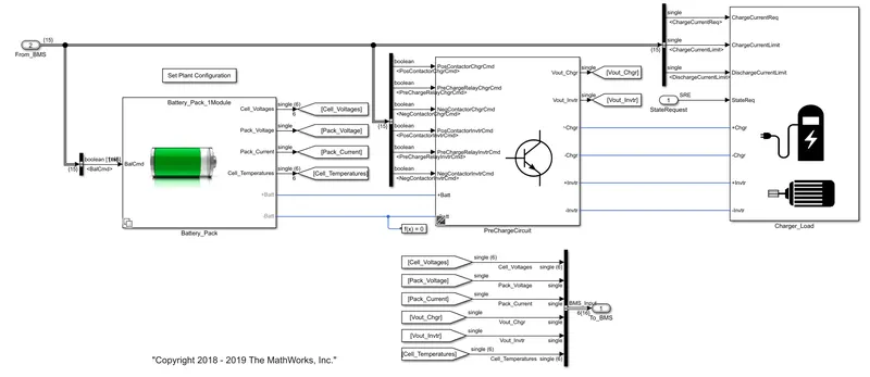
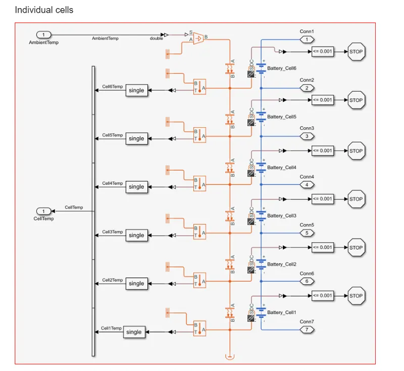
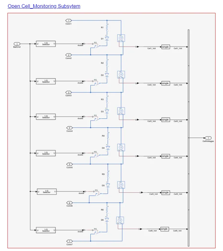
PreCharge Circuit
Closed Loop Simulation of BMS Algorithms
The harness dashboard:
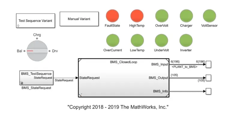
- The harness dashboard is shown. It consists of the test sequence variant subsystem which hold a three different test cases. This dashboard also helps in determining the fault states and other parameters as shown in the diagram below. Green color indicates that the system is working without any errors while red signal will indicate that there is a fault in the system.
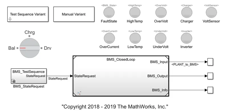
- BMS model can be implemented to check the faults and errors using the three different test cases from the harness dashboard.
TEST SEQUENCE - 1 (No error or Faults)
- To check the faults in the system we have to go to the harness dashboard. Here, in the first compilation the test case 1 is selected.
There are three stages of driving condition, namely-
- Driving
- Charging
- Standby
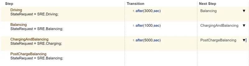
- When the simulation begins, initially the vehicle is in driving state and the SOC will decrease for this time period. After a time period of 3000 seconds the next step is balancing mode and the vehicle is in standby condition. After, another 1000 seconds, the vehicle is in charging phase and the battery's SOC increases almost to 100%. The next phase is the post charging phase in which the vehicle again goes for the standby mode.
RESULTS
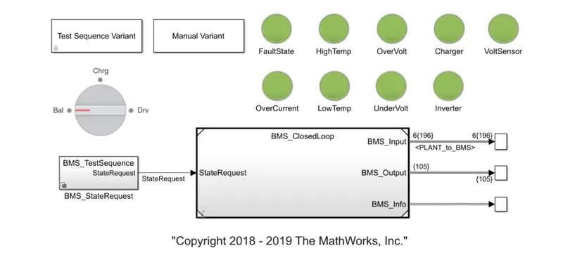
- Here all the indicators are green. So there are no errors, we check the plot and it is represented below
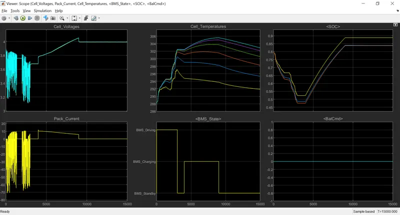
- Let us define the following points from the scope results, The input cycle can be seen on the BMS_State plot, where the vehicle is first driven, then charged to SOC = 90% and then into standby mode. The battery pack voltage increases to 4.2V when charging. During the driving and charging cycle, the cell temperature rises and begins to fall into standby mode. After the driving cycle the SOC drops below 50% and then shifts to charging until the SOC reaches 100%. The current supplied to the EV during the driving phase can be seen in the current plot.
TEST SEQUENCE - 2 (High Temperature Fault)
- For this we have to go to test case variant subsystem and select test case 2 from there and click on "Ok". Then we have to run the system for the given simulation time. The result shows that there is a fault condition in the vehicle.
- This test case has two Phases for the battery pack, i.e., Driving and Charging phases.
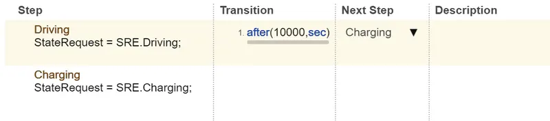
- The dashboard on the model depicts the same with a red colour indication.
RESULTS
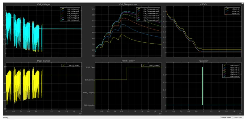
- The scope shows the various parameters for the BMS model under second test case. After 10,000 sec when the driving cycle is over, the fault condition occurs and so the SOC does not increase even for the charging phase.
TEST SEQUENCE - 3 (Charging - No fault)
- The last test is for the third test sequence. For this, we have to go to test case variant subsystem and select test case 3 from there and click on "Ok".
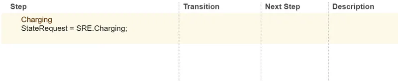
- There is only a single phase here for the third test case, i.e., the charging phase.
RESULTS
- After running the simulation. The dashboard shows no errors or faults.
- The scope shows the results for the third test case,
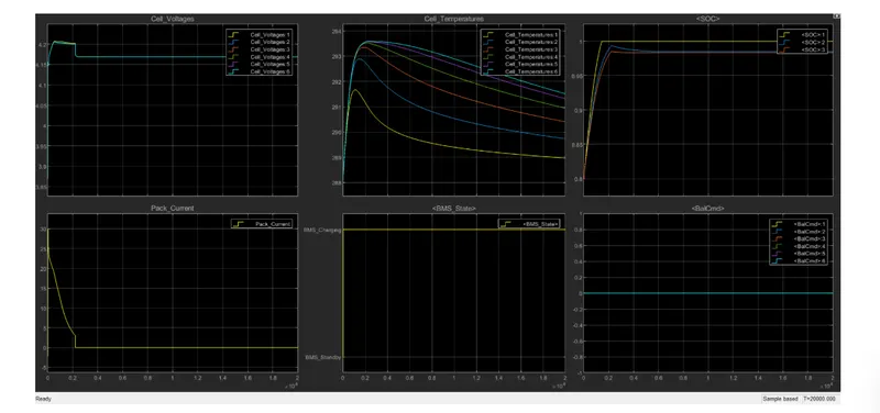
- Here the SOC increases from 80 to 100% and then remain in standby mode. After the standby mode was achieved, the cell temperature also dropped to its optimum value.
CONCLUSION
- Hence, the BMS model was implemented to check for faults and errors using three different test cases from the Harness dashboard.
Q) What is coulomb counting? Refer to the above model and explain how BMS implements coulomb counting for SOC estimation?
Coulomb Counting
- Coulomb counting involves measuring the amount of current flowing into or out of the battery. The ‘coulomb counting’ or CoulCount method was developed by Schmitt et al.
- Laptops, medical equipment and other professional portable devices use coulomb counting to estimate SoC by measuring the in-and-out-flowing current. Ampere-second (As) is used for both charge and discharge. The name “coulomb” was given in honor of Charles-Augustin de Coulomb (1736–1806) who is best known for developing Coulomb’s law
To determine available capacity, coulomb counting relies on the integration of the current drawn from and supplied to a battery over time, `τ∈[t0,t ]`, as given by
`SOC(t)=SOC(t0)−∫_(t0)^t(η(τ)I(τ))/(C_b^o)dτ`
where I is the current and η is the efficiency during charge and discharge operations
- Coulomb counting is advantageous in terms of a simple structure and its ease of implementation. However, some problems make it difficult to accurately estimate battery SOC by coulomb counting. Because battery capacity and efficiency are significantly influenced by operating temperature and current direction, these factors should be considered to correct for battery SOC.
- Sensor accuracy is also important because accumulated errors can lead to a drift in the estimated battery SOC. Furthermore, one of the main problems in coulomb counting is that it is necessary to calibrate the initial battery SOC.
How BMS implements coulomb counting for SOC estimation
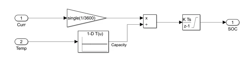
- The pack current in Coulomb (in ampere seconds) is converted to Ah (ampere hours) by dividing it by 3600, and then dividing by the rated capacity gives an idea of the remaining capacity of the battery, and integrating that value with the discrete time integrator, to provide soc estimation throughout the simulation run.
- The rated capacity is determined by a 1D lookup table with battery temperature input.