Week 7 State of charge estimation
Week 7 State of charge estimation
Aim
To analyze ‘Design and Test Lithium-Ion Battery Management Algorithms’ mat lab file
Objectives
- To simulate 3 test cases from the harness dashboard and write a detailed report on the result.
- To define coulomb counting and explain how BMS implements coulomb counting for SOC estimation on the selected files.
Here we have to study the mat lab file which is given and we must prepare a report for its analysis. The citation for the file is given as follows.
Chirag (2021). Design and Test Lithium-Ion Battery Management Algorithms (https://www.mathworks.com/matlabcentral/fileexchange/72865-design-and-test-lithium-ion-battery-management-algorithms)
This example project can be used as a reference design to get started with designing a Lithium-Ion Battery Management System (BMS) with MATLAB and Simulink.
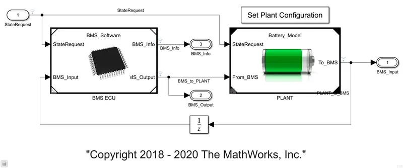
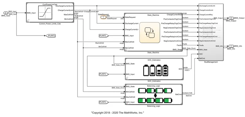
The project includes Simulink models for BMS Algorithms such as:
- State of Charge estimation using Extended Kalman Filter, Unscented Kalman Filter
2. Passive Battery Cell Balancing
3. State Machine for Pre-charging and Contactor Management
4. Fault Management - Over/Under Voltage, Over Current, Over Temperature etc.
5. Charge and Discharge Current Limit Calculations
To design and test these algorithms, the project also includes files for
1. Li-ion Battery Cell Parameter Estimation
2. Battery Pack with 6 cells in series and 96 cells in series
3. Simulink Test files with test cases to test State Machine Logic
4. Linking requirements to Models
Now, our first objective is to simulate 3 test cases from the harness dashboard. For that, select the harness dashboard from the project file which we downloaded. The battery model harness dashboard is represented below.
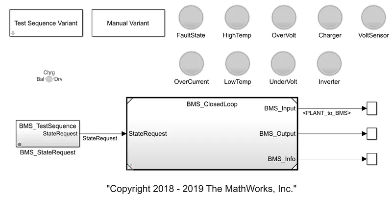
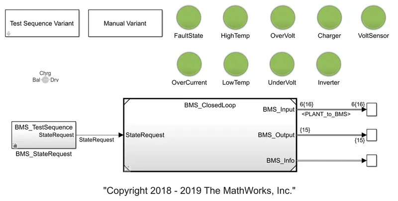
This model contains three test cases and some indicators as in representation to notify errors. We can select the first test condition as given below.
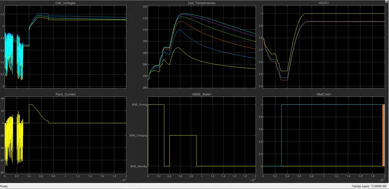
From test one case properties, we can see that it has three conditions. Driving, charging, and standing by. When simulation will start, the model will be in driving condition. After 3000 seconds it will be in standby mode and after 1000 seconds it will be in charging mode.
From the plot, we can say that the vehicle is initially in a driving state, and charging was done to 90%. After charging it went to standby mode. It can be seen in the BMS state plot. Battery voltage was increased to 4.2V while charging. Battery temperature increases in driving and charging. It remains constant in standby mode. The current plot shows the value of current supplied to the vehicle while driving. SOC decreased up to 50% in driving conditions and it was increased while charging.
Coulomb counting
It is a method used for estimating the state of charge (SOC) of a battery. The coulomb counting method is expedient for state-of-charge (SOC) estimation of lithium-ion batteries with high charging and discharging efficiencies. The charging and discharging characteristics are investigated and reveal that the coulomb counting method is convenient and accurate for estimating the SOC of lithium-ion batteries. The Coulomb counting method measures the discharging current of a battery and integrates the discharging current over time in order to estimate SOC. Coulomb counting method is done to estimate the soc (t), which is estimated from the discharging current, I(t), and previously estimated SOC values, SOC(t-1). SOC is calculated by the following equation:
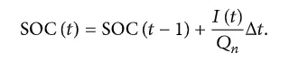
But there are several factors that affect the accuracy of the Coulomb counting method including temperature, battery history, discharge current, and cycle life. To improve the Coulomb counting method, a new technique called the modified Coulomb counting method is proposed. The modified Coulomb counting method uses the corrected current to improve the accuracy of estimation.
The corrected current is the function of discharging current. There is a quadratic relationship between the corrected current and discharging current of the battery. By the practice of experimental data, the corrected current is calculated by the following form:
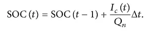
When comparing both counting methods, the modified Coulomb counting method shows better results.
Observations:
Test case: 1
- During charging the battery pack voltage is increased up to 4.2V.
- The input cycle in which the vehicle initially undergoes driving, then charging till SOC becomes 90% and then later in the standby state.
- The cell temperature increases during the driving and charging cycle and starts falling off in standby mode.
- The SOC drops to less than 50% after the driving cycle and is then later put into charging until SOC reaches 100%.
Test case 2:
- After 10,000 sec when the driving cycle is over, the fault condition occurs and so the SOC does not increase even for the charging phase
- Cell temperature increases during driving and since it is higher than recommended, BMS stops the battery from charging, so we can see a gradual decrease in temperature.
Test case: 3
- The SOC increases from 80 to 100% and then remains in standby mode.
- During charging SOC increases from 80 to 100% temperature increases charging and is reduced in the standby state of the BMS.
Conclusion:
Thus, Design and Test Lithium-Ion Battery Management Algorithms model have been analyzed, and coulomb counting has been studied in the estimation of the SOC of the battery.