Week - 4
1. Washing Machine using State Flow
The simulink file for "Washing machine using state flow" model is uploaded in google drive and the access link to the file is
https://drive.google.com/file/d/14kjq4nPMJLm8kZOCYKSFbmeHeQchG0Ar/view?usp=sharing
Objective:
To implement control logic of a washing machine using state flow as per given conditions.
Conditions:
- If the power is available, the system gets activated.
- If the water supply is not available, stop the process and indicate through LED.
- Soaking time should be 200s followed by washing time of 100s.
- Then rinsing happens for the next 20s and dryer runs for 50s.
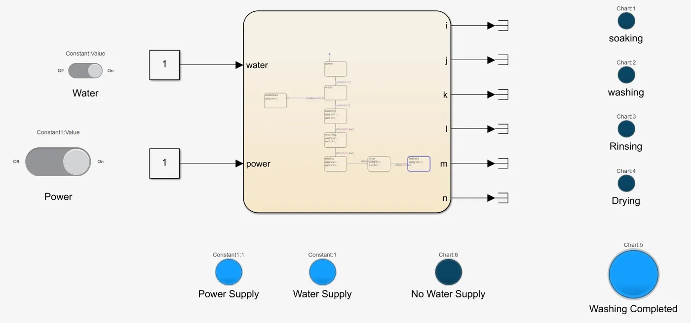
- After all the process have completed turn on the finished LED.
Descriptions:
The control logic of the washing machine can be achieved by state flow control by using components such as chart block, constant block, slider switch, terminator, and lamps from the dashboard.
Simulink Model:
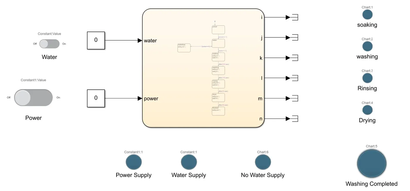
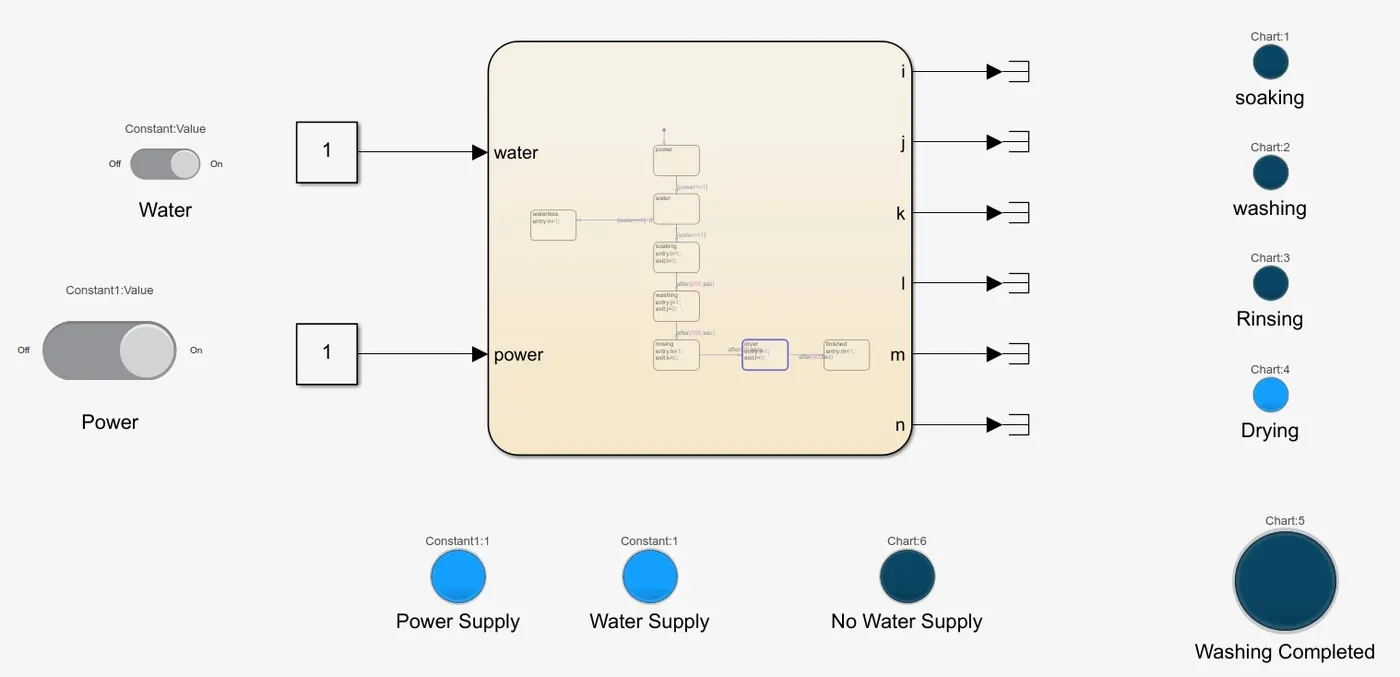
In this Simulink model power and water are the two inputs used to trigger the working process. Each input ports are made enabled with slider switches followed by constant blocks to give signals to the chart through input ports.
Chart Implemented:
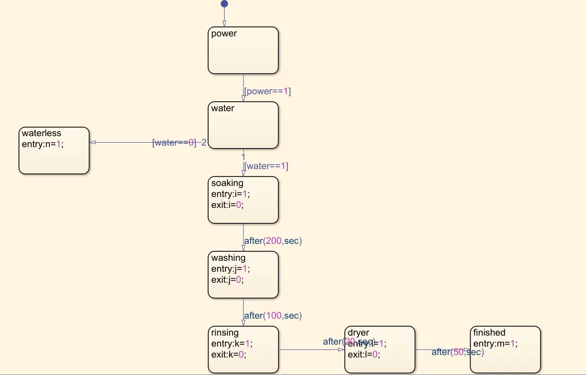
The above picture shows the implementation of state flow for running a washing machine. The chart is being implemented in a way that the input from the Simulink system reaches to power state in the chart and the process starts. Then it reaches the water state, if the water supply is not enabled process stops and indicates it through a lamp, and if the water supply is enabled, the process steps to the next state i.e. soaking process.
The soaking process will be carried out for about 200secs, while soaking process is been carrying the lamp declared for soaking process will be in active state indicating that soaking is under process. After the washing state will be active. The washing state is meant to be carried out for 100secs. While washing process is under process lamp meant for washing state will be active.
Then the rinsing state is activated for 20secs along with a separate lamp and finally drying process is undergone for about 50secs, as the washing process is finished, the final state is activated in order to indicate that the process has been successfully carried out through a lamp. The delays for the states are implemented using conditions in between the states as shown in the chart.
There are six output ports used for the indication of soaking, washing, rinsing, drying, no water supply, and process completion. Each output is connected to separate lamps and then terminated in order to eliminate the warnings.
Results:
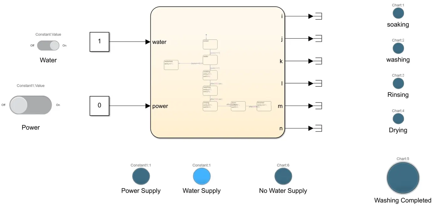
Case:1 Power supply is Off, water supply is ON
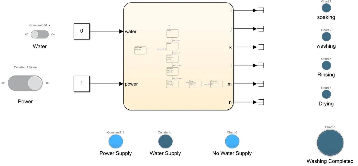
Case:2 Power supply ON, water supply OFF
Case:3 Power supply ON, water supply ON
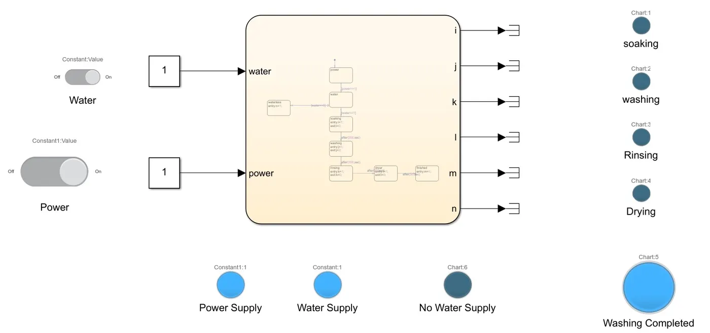
Case:4 Soaking under process
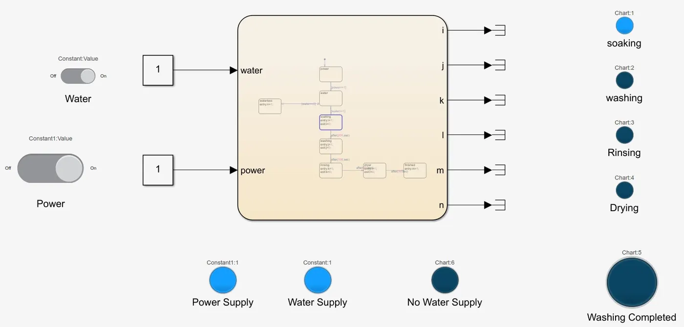
Case:5 Washing under process
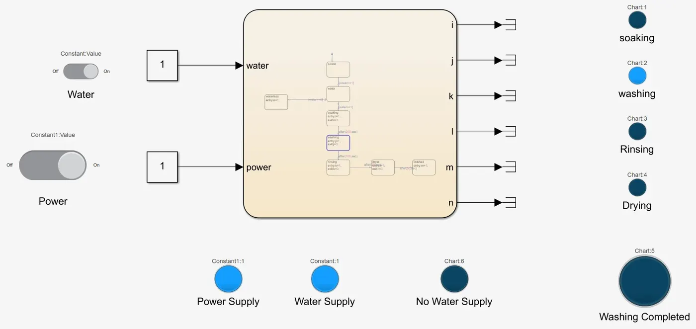
Case:6 Rinsing under process
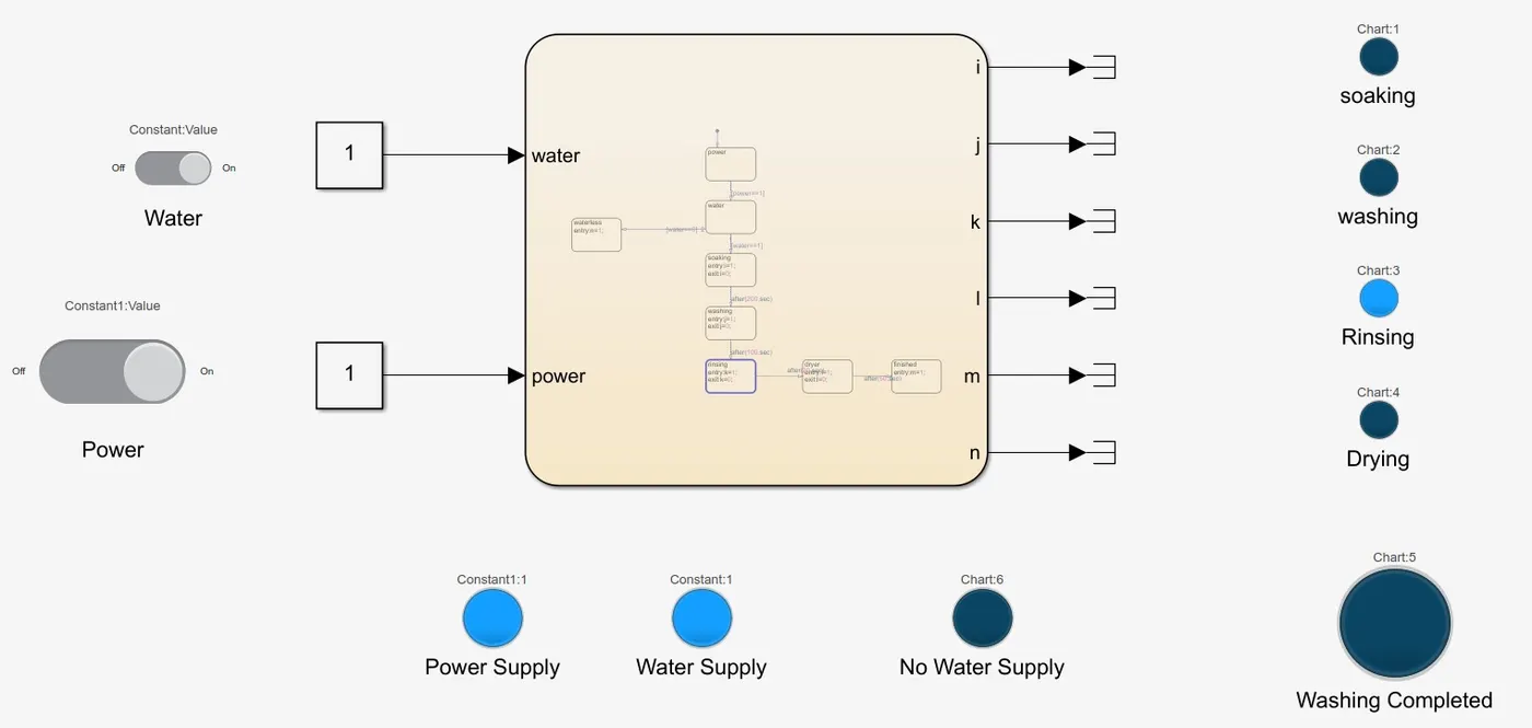
Case:7 drying under process
Case:8 Washing process completed
Conclusions
All the process under the washing machine has been executed along with the conditions given.
2. Gear shift indicator using state flow
The simulink file for the model "Gear shift" is uploaded on google drive and the access link to the file is
https://drive.google.com/file/d/1FxB1XPwLDa9Ep2ySeM1cNKPn1GPYfXn2/view?usp=sharing
Objective:
To make a Simulink chart for the gear shift logic with the given conditions.
Conditions:
|
Speed range |
Gear |
|
0 - 15 |
1 |
|
16 - 25 |
2 |
|
26 - 40 |
3 |
|
41 - 60 |
4 |
|
61- above |
5 |
Description:
Gear shifter indicator can be achieved by state flow by using components such as slider gain block, constant block, chart, terminator, display, custom gauge.
Simulink model:
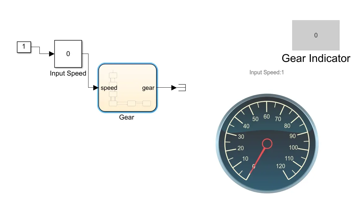
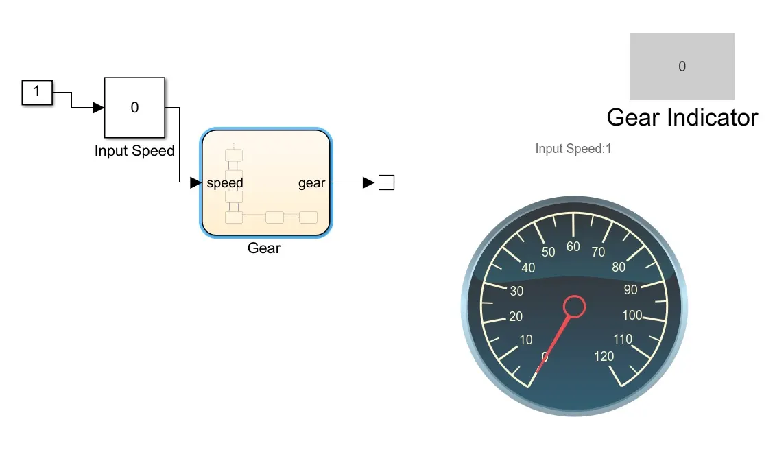
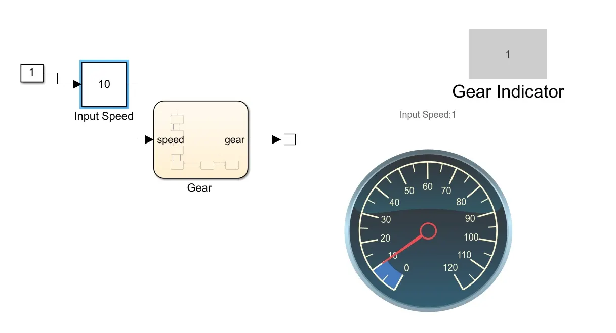
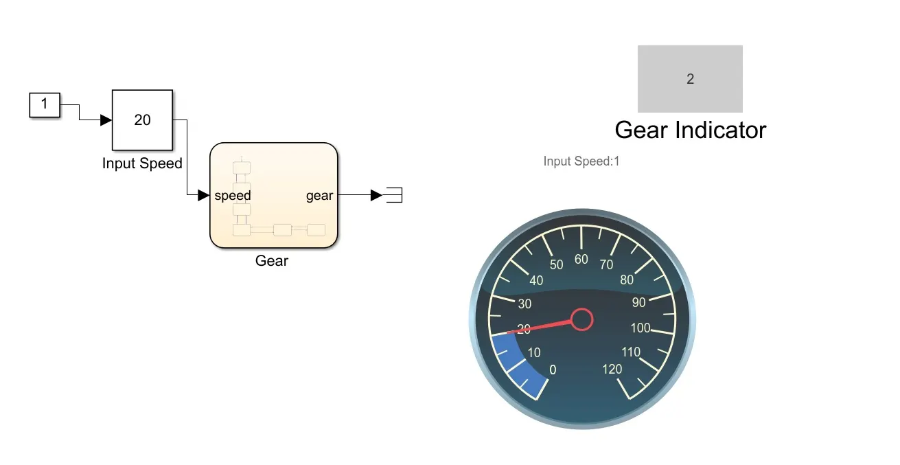
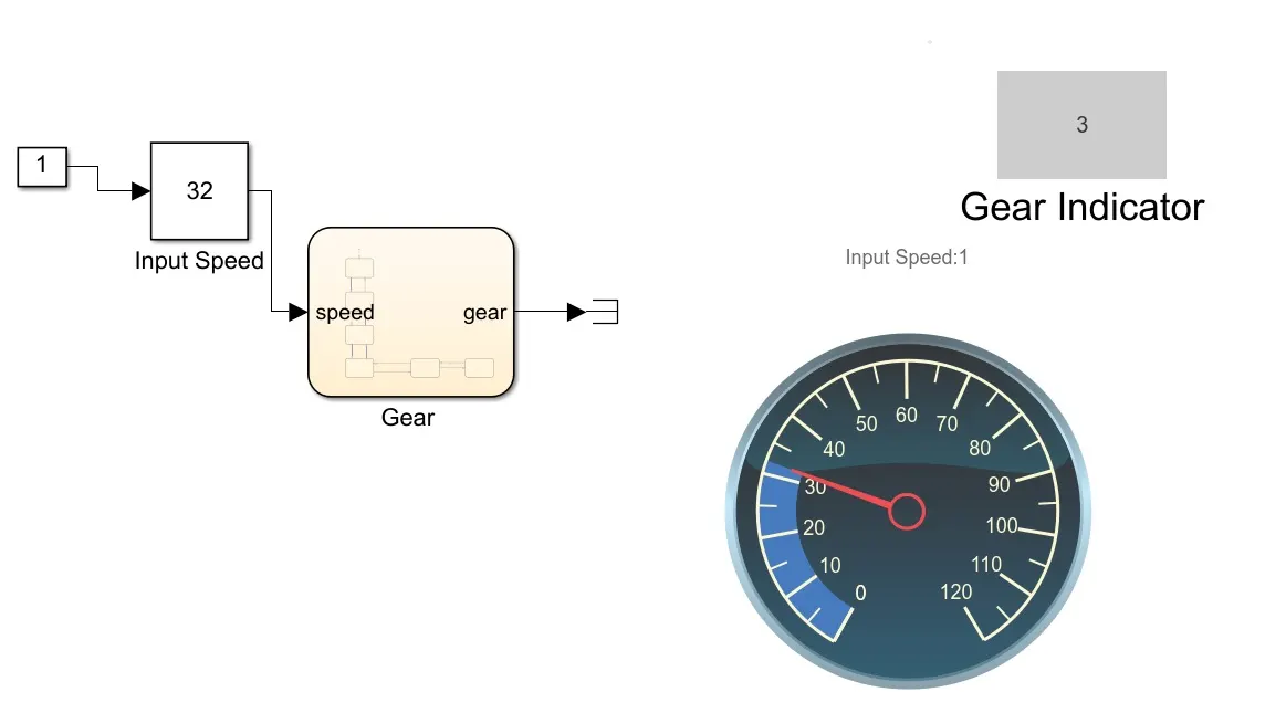
The above Simulink chart is modeled to function as a gear shift indicator which indicates the gear engaged for the given speed with respect to given conditions. Speed is given as input through slider gain block, which enables us to vary the speed while running simulation.
Chart Implemented:
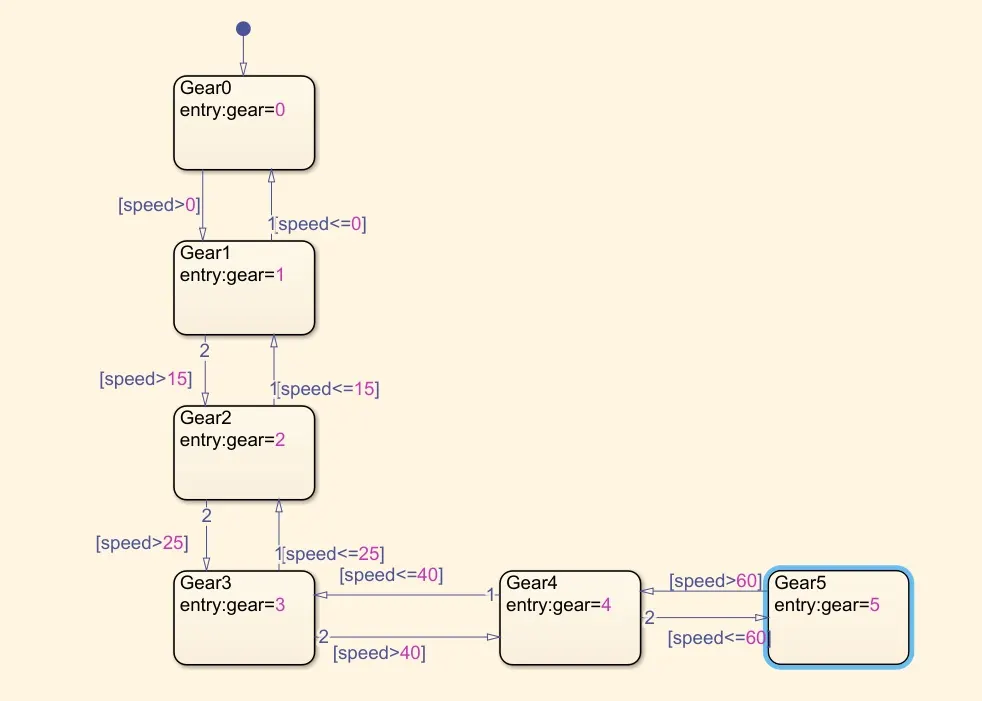
The above shown chart implements logical conditions for gear indicator in order to execute the given conditions, which is achieved by using transition and states. When input speed is given through the input port first state, Gear0 is reached. And when the speed is greater than 0, “Gear1” state is activated. If the speed exceeds 15kmph “Gear2” will be active or else if speed is below or equal to 0, first state “Gear0” will be in active again. When speed range is between 25kmph and 40kmph “Gear3” state will be active. Likewise, logical conditions are declared up to 60kmph and above with gears engaged up to 5 for both upshifts and downshifts with respect to the speed range.
Results
Case:1 Speed is 0kmph
Case:2 speed is 10kmph
Case:3 speed is 20kmph
Case:4 Speed is 32kmph
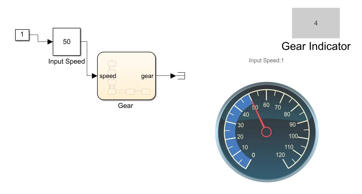
Case:5 Speed is 50kmph
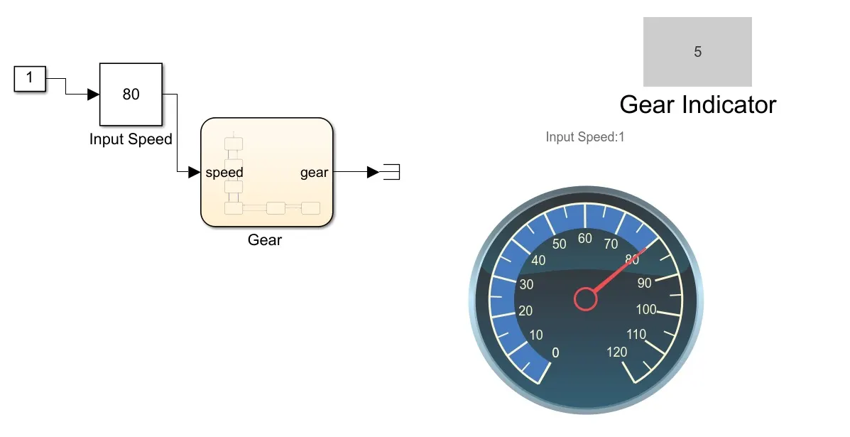
Case:6 Speed is 80kmph
Conclusions:
A gear shift indicator is created using Simulink chart and successfully executed with given conditions.