Week 7: Shock tube simulation project
OBJECTIVE:
We will be simulating a transient shock tube problem and observing the result
GEOMETRY:
The following geometry has been provided:
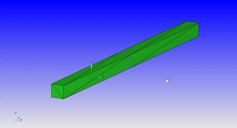
It consists of two cuboids joined together, we will delete the joining face highlighted by the purple outline and our geometry is ready to be used.
BOUNDARY FLAGGING:
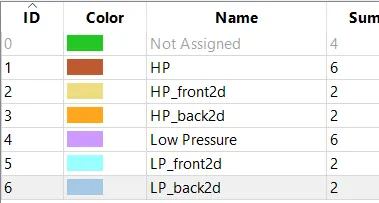
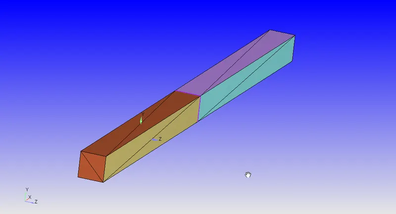
BOUNDARY CONDITIONS:
The 2D boundaries are marked as 2D.
The High and Low-Pressure Boundaries are marked as Slip Walls.
INITIAL CONDITIONS:
The high-pressure region is set to be filled with Nitrogen at 6 Bars and 300K.
The Low-pressure region is filled with Oxygen at 1 Bar and 300K.
EVENTS:
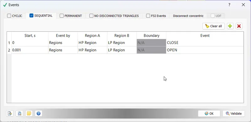
We have set up an event to simulate the popping of a diaphragm between low-pressure and high-pressure regions:
MESHING:
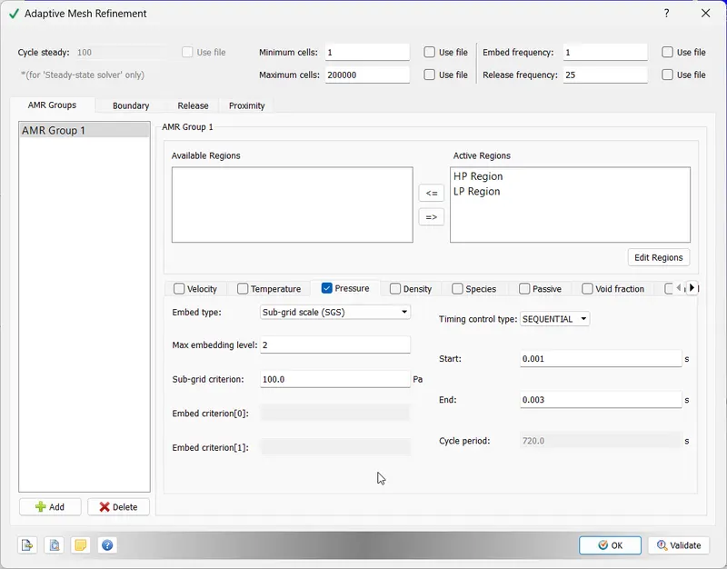
We are using a base mesh of 0.1 mm and an Adaptive Mesh Refinement on top of it:
SOLVER AND PHYSICAL MODELS:
We use a density-based transient solver and the K-epsilon model with default values.
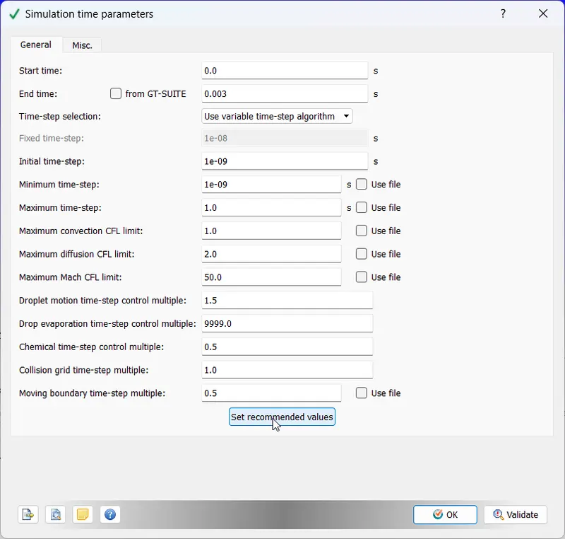
Time Parameters:
RESULTS:
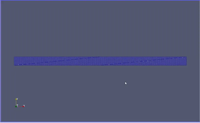
MESH GENERATION:
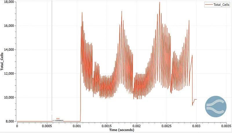
CELL COUNT:
TEMPERATURE CONTOUR:
PRESSURE CONTOUR:
CONCLUSION:
- As the regions are opened to each other, high-pressure N2 rushes towards O2 at low-pressure, compressing it in the process and creating a high-temperature zone. This is why we see higher temperatures in low-pressure regions in the beginning.
- When the N2 rushes towards the O2 region, pressure is relieved in its rear end, creating a lower temperature and lower pressure region at the rear of N2.
- This new pressure difference invokes N2 to travel backwards, relieving pressure in the O2 region.
- This altercation of the pressure region continues back and forth until pressure is stabilized.