Week 7: Shock tube simulation project
Aim:
To simulate the shock tube problem to understand the concepts of regions and events in CONVERGE.
Objectives:
- Setup the transient shock flow case using the CONVERGE Studio
- Simulate the shock tube problem
- Postprocess the simulation results using Paraview and CONVERGE Studio
Geometry:
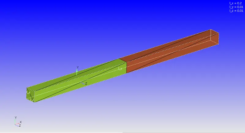
The geometry is a box of length 0.2 m, width and breadth of 0.1 m in the x, y and z directions respectively. The geometry is divided into two halves: the high pressure zone which contains the nitrogen and the low pressure zone which contains the oxygen. In the real world, the box is seperated by a diaphragm but in the computational model we use the concept of 'events', which help to seperate the two sections.
The high and low pressure zone of the shock tube along with the dimensions are illustrated in the following figure
Case Setup:
The case setup tree for the shock tube problem was setup in the following manner:
- Application type:
- Since the problem is general flow problem, we choose the time based application.
- Materials:
- Since the problem includes the flow of gases, a gas simulation model is chosen.
- The global transport properties are set to the default settings.
- The gas species used for this problem is Nitrogen and Oxygen.
- Simulation parameters:
- The simulation model is transient, fully hydrodynamic and compressible in nature
- The total simulation time is 3 milliseconds and the time stepping is set to be variable based on the CFL criteria. The initial and the minimum time step is set to `10^{-9}` seconds and the maximum time step is set to 1 second.
- The Navier-Stokes equation solver is a density based PISO algorithm with the default settings.
- Boundary Conditions:
- All the boundaries (the high pressure and the low pressure regions) in the problem are stationary, slip walls and default settings for the turbulence dissipation and turbulent kinetic energy.
- Initial Conditions and Events:
- The high pressure region is initialized with 6 bar pressure and pure nitrogen while the low pressure region is initialized with pressure set to 1 atm and filled with pure oxygen.
- An 'event' has been set to model the breaking of the diaphragm seperating the two regions. The disconnected triangles formed by the event stay intact till 1 millisecond and then reamin open for rest of the simulation.
- Physical Models
- We use a standard RANS RNG model for the simulation with the standard wall functions for the near wall treatment.
- Grid Control
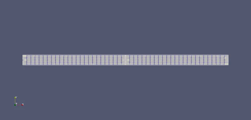
- The base grid is set to 0.004m in the x-direction, 0.001m in the y and z direction respectively.
- An adaptive mesh refinment is set up for refining the mesh by tracking the Nitrogen concentration.
The mesh generated from the above setup is as follows:
Simulation Results:
The contours and the line plots for the simulation are as follows:
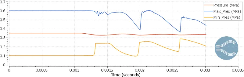
The mean, maximum and the minimum pressure in the domain with respect to time
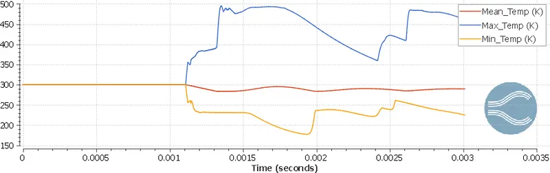
The mean, maximum and the minimum temperature in the domain with respect to time
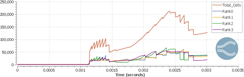
Variation of the total cell count and cells assigned to each processor
Animation of the velocity and Nitrogen massfraction : Animation Link
From the above plots, we can derive the following conclusions:
- From the contours and the line plots, we can observe that for time 0.001 seconds no interaction is taking place between the regions. Hence, we can conclude that we have successfully seperated the two regions
- When the disconnected triangles are removed by the solver, there is a small delay after which shocks are generated in the domain which is observed by the sharp increase in the number of the temperature, pressure and the number of the cell elements
- From the pressure and temperature line plots and animation, we observe that the flow disturbances are perodic in nature and are decaying. This observation is inline with the theortical expectation that when the two regions are connected the steady state result should reach to a mean value.
Conclusions:
This project on the shock has helped us to understand the concept of the events and regions on an advanced level which will be beneficial to model complex engineering machinery like engines and turbines.