Week 8 - Simulation of a backward facing step in OpenFOAM
Aim:
To simulate incompressible-laminar-viscous flow through backward facing step geometry using OpenFOAM and understand the effects of the simpleGrading on fluid properties
Solution:
The procedure to setup and simulate the current problem in OpenFOAM is as follows:
- Copy a tutorial case from $FOAM_TUTORIALS of transient, incompressible, laminar flow in a separate directory and change the system/blockMeshDict file for modifying the geometry, blocks and mesh. (the changes are provided further below in the report)
- After setting up the blockMeshDict file, generate the constant/polyMesh directory by using the 'blockMesh' command in the terminal and for checking the integrity of the mesh by using the 'checkMesh' command in the terminal.
- To provide intial and boundary conditions, we modify the 0/p and 0/U.
- The initial conditions for both fluid properties are set as uniformly zero throughout the interior of the domain.
- For Velocity, a uniform velocity of 0.1 is provided as the inlet boundary condition, zeroGradient is provided at the outlet, no slip conditons applied at the side-walls and empty boundary conditons are applied in the Z-direction, since we are solving a 2D problem.
- For Pressure, zeroGradient is provided at the inlet at the side-walls, a uniform value of 0 is provided at the outlet, and empty boundary conditons are applied in the Z-direction, since we are solving a 2D problem.
- Keep the value of `nu` in constant/transportProperties as 0.01, since for given values of reference velocity and reference length the flow is laminar because of Reynolds number ~1.
- An appropriate time step is chosen in the system/controlDict such that CFL criteria (Co < 1) is satisfied everywhere in the domain.
- The system/fvSchemes and system/fvSolution have not been modified.
- Start the simulation by providing the command 'icoFoam' in the terminal
OpenFOAM provides basic tools for varying the finite volume dimensions in the system/blockMeshDict file. One of the prominent features is the simpleGrading. It is defined as the ratio of final cell length by the initial cell length in a block in a specific direction. Mathematically, it can be represented as follows,
`simpl eGradi ng = {Fi nal\ cell\ l eng th}/{Initial\ cell\ l eng th}`
To understand the effects of the simpleGrading on the fluid properties, we test the current problem with uniform grading everywhere (simpleGrading = 1 in all directions and blocks) versus the fine mesh near the walls (simple Grading = 0.2)
Case1: simpleGrading = 1
For this problem, we setup the system/blockMeshDict file as follows
- Domain is defined using 16 verticies and divided into 3 blocks
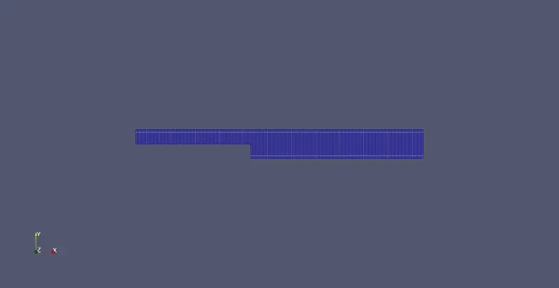
- The blocks have been meshed in a particular manner so that the total number of cells in x-direction are 200 while the number of y-direction is 20
- simpleGrading is set as one for all blocks and in all directions
- The patches are assigned with proper names and proper orientation.
/*--------------------------------*- C++ -*----------------------------------*\
  =========                 |
  \\      /  F ield         | OpenFOAM: The Open Source CFD Toolbox
   \\    /   O peration     | Website:  https://openfoam.org
    \\  /    A nd           | Version:  9
     \\/     M anipulation  |
\*---------------------------------------------------------------------------*/
FoamFile
{
    format      ascii;
    class       dictionary;
    object      blockMeshDict;
}
// * * * * * * * * * * * * * * * * * * * * * * * * * * * * * * * * * * * * * //

convertToMeters 0.1;

vertices
(
    (0 0 0)  		//0
    (0.8 0 0)  		//1
    (0.8 -0.1 0) 	//2
    (2 -0.1 0)   	//3
    (2 0   0)           //4
    (2 0.1 0)   	//5
    (0.8 0.1 0) 	//6
    (0 0.1 0) 		//7

    (0 0 0.1) 		//8
    (0.8 0 0.1)  	//9
    (0.8 -0.1 0.1)  	//10
    (2 -0.1 0.1)  	//11
    (2 0   0.1)         //12
    (2 0.1 0.1)   	//13
    (0.8 0.1 0.1) 	//14
    (0 0.1 0.1)   	//15
);

blocks
(
    hex (0 1 6 7 8 9 14 15) (80 20 1) simpleGrading (1 1 1)
    hex (2 3 4 1 10 11 12 9) (120 20 1) simpleGrading (1 1 1)
    hex (1 4 5 6 9 12 13 14) (120 20 1) simpleGrading (1 1 1)
);

edges
(
);

boundary
(
    Inlet
    {
        type patch;
        faces
        (
            (0 7 15 8)
        );
    }
    Outlet
    {
        type patch;
        faces
        (
            (4 3 11 12)
            (5 4 12 13)
        );
    }
    fixedWalls
    {
        type wall;
        faces
        (
            (0 8 9 1)
            (1 9 10 2)
            (2 10 11 3)
            (7 6 14 15)
            (6 5 13 14)
        );
    }
    frontAndBack
    {
        type empty;
        faces
        (
            (0 1 6 7)
            (1 2 3 4)
            (4 5 6 1)
            (8 15 14 9)
            (9 12 11 10)
            (14 13 12 9)
        );
    }
);

mergePatchPairs
(
);

// ************************************************************************* //
All the other modified files described earlier are as follows:
The initial and boundary conditions of velocity (0/U)
/*--------------------------------*- C++ -*----------------------------------*\
  =========                 |
  \\      /  F ield         | OpenFOAM: The Open Source CFD Toolbox
   \\    /   O peration     | Website:  https://openfoam.org
    \\  /    A nd           | Version:  9
     \\/     M anipulation  |
\*---------------------------------------------------------------------------*/
FoamFile
{
    format      ascii;
    class       volVectorField;
    object      U;
}
// * * * * * * * * * * * * * * * * * * * * * * * * * * * * * * * * * * * * * //

dimensions      [0 1 -1 0 0 0 0];

internalField   uniform (0 0 0);

boundaryField
{
    Inlet
    {
        type            fixedValue;
        value           uniform (0.1 0 0);
    }
    Outlet
    {
        type            zeroGradient;
    }
    fixedWalls
    {
        type            noSlip;
    }

    frontAndBack
    {
        type            empty;
    }
}

// ************************************************************************* //
The initial and boundary conditions of velocity (0/p)
/*--------------------------------*- C++ -*----------------------------------*\
  =========                 |
  \\      /  F ield         | OpenFOAM: The Open Source CFD Toolbox
   \\    /   O peration     | Website:  https://openfoam.org
    \\  /    A nd           | Version:  9
     \\/     M anipulation  |
\*---------------------------------------------------------------------------*/
FoamFile
{
    format      ascii;
    class       volScalarField;
    object      p;
}
// * * * * * * * * * * * * * * * * * * * * * * * * * * * * * * * * * * * * * //

dimensions      [0 2 -2 0 0 0 0];

internalField   uniform 0;

boundaryField
{
    Inlet
    {
        type            zeroGradient;
    }
    Outlet
    {
        type            fixedValue;
        value		uniform 0;
    }
    fixedWalls
    {
        type            zeroGradient;
    }

    frontAndBack
    {
        type            empty;
    }
}

// ************************************************************************* //
The inputs for the simulation (system/controlDict file). We run the simulation only for 0.5 seconds, since it attains fully developed solutions.
/*--------------------------------*- C++ -*----------------------------------*\
  =========                 |
  \\      /  F ield         | OpenFOAM: The Open Source CFD Toolbox
   \\    /   O peration     | Website:  https://openfoam.org
    \\  /    A nd           | Version:  9
     \\/     M anipulation  |
\*---------------------------------------------------------------------------*/
FoamFile
{
    format      ascii;
    class       dictionary;
    location    "system";
    object      controlDict;
}
// * * * * * * * * * * * * * * * * * * * * * * * * * * * * * * * * * * * * * //

application     icoFoam;

startFrom       latestTime;

startTime       0;

stopAt          endTime;

endTime         0.5;

deltaT          1e-5;

writeControl    timeStep;

writeInterval   2.5e3;

purgeWrite      0;

writeFormat     ascii;

writePrecision  6;

writeCompression off;

timeFormat      general;

timePrecision   6;

runTimeModifiable true;


// ************************************************************************* //
Case 2: Grading Factor = 0.2 (Finer mesh near the walls)
In this case, only the system/blockMeshDict file is modified rest all files have been kept the same.
The changes in the system/blockMeshDict are as follows:
- The geometry is now defined using 22 vertices and 5 blocks
- The blocks have been meshed in a particular manner so that the total number of cells in x-direction are 200 while the number of y-direction is 20
- The simpleGrading in the blocks have been set to 0.2 or 5 depending the definition of the block and if the sidewalls are associated with the first cell or the last cell
- he patches are assigned with proper names and proper orientation.
/*--------------------------------*- C++ -*----------------------------------*\
  =========                 |
  \\      /  F ield         | OpenFOAM: The Open Source CFD Toolbox
   \\    /   O peration     | Website:  https://openfoam.org
    \\  /    A nd           | Version:  9
     \\/     M anipulation  |
\*---------------------------------------------------------------------------*/
FoamFile
{
    format      ascii;
    class       dictionary;
    object      blockMeshDict;
}
// * * * * * * * * * * * * * * * * * * * * * * * * * * * * * * * * * * * * * //

convertToMeters 0.1;

vertices
(
    (0 0 0)  		//0
    (0.8 0 0)  		//1
    (0.8 -0.1 0) 	//2
    (2 -0.1 0)   	//3
    (2 0   0)           //4
    (2 0.1 0)   	//5
    (0.8 0.1 0) 	//6
    (0 0.1 0) 		//7


    (0 0 0.1) 		//8
    (0.8 0 0.1)  	//9
    (0.8 -0.1 0.1)  	//10
    (2 -0.1 0.1)  	//11
    (2 0   0.1)         //12
    (2 0.1 0.1)   	//13
    (0.8 0.1 0.1) 	//14
    (0 0.1 0.1)   	//15

    (0 0.05 0)		//16
    (0.8 0.05 0)	//17
    (2	0.05 0)		//18

    (0 0.05 0.1)	//19
    (0.8 0.05 0.1)	//20
    (2	0.05 0.1)	//21


);

blocks
(
    hex (0 1 17 16 8 9 20 19) (80 10 1) simpleGrading (0.2 5 1)
    hex (16 17 6 7 19 20 14 15) (80 10 1) simpleGrading (0.2 0.2 1)
    hex (2 3 4 1 10 11 12 9) (120 20 1) simpleGrading (5 5 1)
    hex (1 4 18 17 9 12 21 20) (120 10 1) simpleGrading (5 5 1)
    hex (17 18 5 6 20 21 13 14) (120 10 1) simpleGrading (5 0.2 1)
);

edges
(
);

boundary
(
   Inlet
    {
        type patch;
        faces
        (
            (0 16 19 8)
            (16 7 15 19)
        );
    }
    Outlet
    {
        type patch;
        faces
        (
            (4 3 11 12)
            (18 4 12 21)
            (5 18 21 13)
        );
    }
    fixedWalls
    {
        type wall;
        faces
        (
            (0 8 9 1)
            (1 9 10 2)
            (2 10 11 3)
            (7 6 14 15)
            (6 5 13 14)
        );
    }
    frontAndBack
    {
        type empty;
        faces
        (
            (0 1 17 16)
            (16 17 6 7)
            (1 2 3 4)
            (4 18 17 1)
            (18 5 6 17)
            (8 19 20 9)
            (19 15 14 20)
            (9 12 11 10)
            (14 13 21 20)
            (20 21 12 9)
        );
    }
);

mergePatchPairs
(
);

// ************************************************************************* //
Verification:
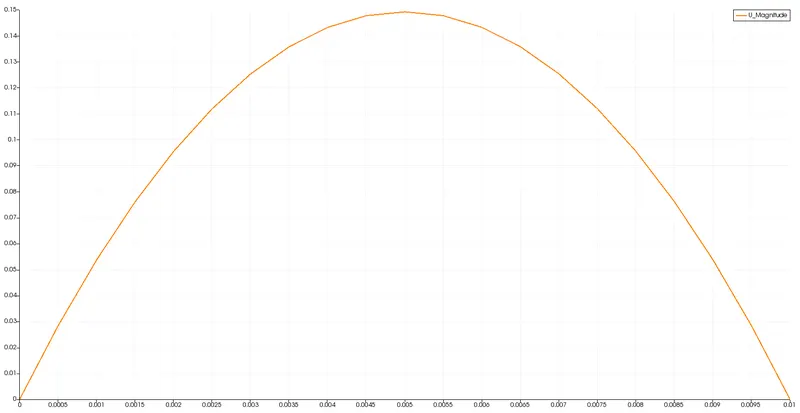
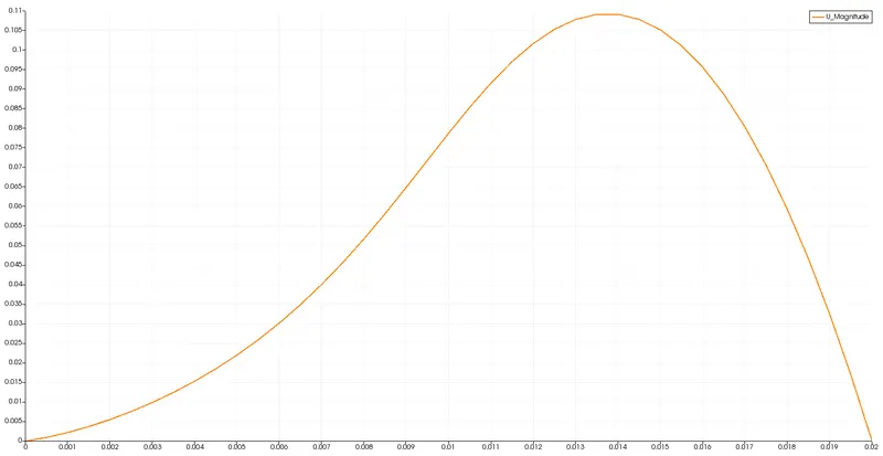
Before summarizing the results, we must verify that the results obtained after 0.5 seconds of flow time are physically consistent. For this, we observe the value of the velocity profile at the x=0.04 from the inlet for both the cases.
From theoritical analysis, for fully developed flow between two parallel plates, the velocity profile should be parabolic and the max velocity should be 1.5 larger than the inlet velocity.
Case 1:
Case 2:
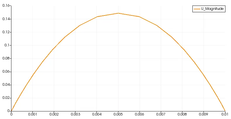
The velocity profile obtained from the simulation are in complete agreement with the theoritical results. Hence, the simulation results are physically consistent and can be used to understand the effects of the flow.
Results:
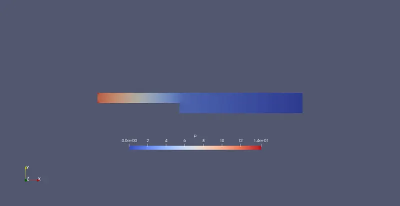
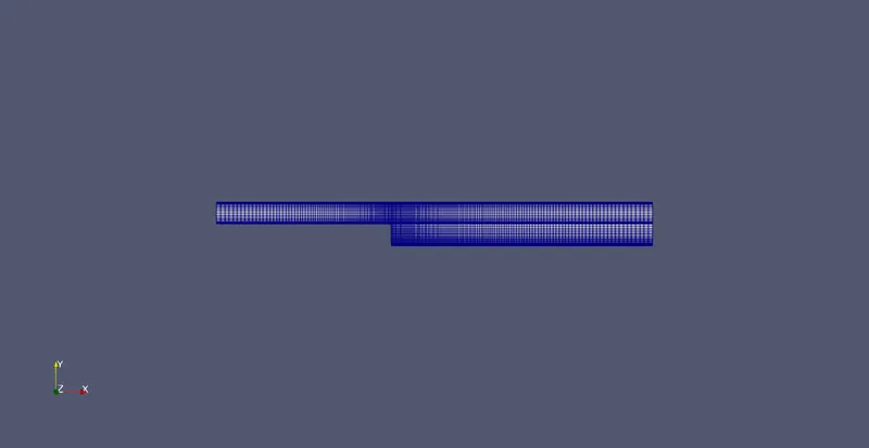
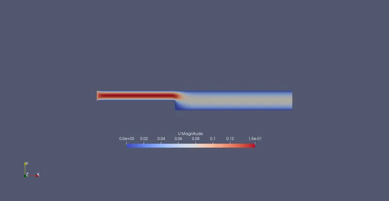
We summarize the results for both the cases and provide figures, contours, graphs, observations and conclusions on the effects of the gridSpacing
Case 1:
Mesh
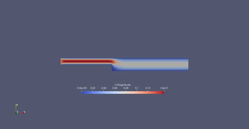
Velocity Contour
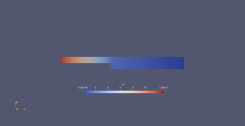
Pressure Contour
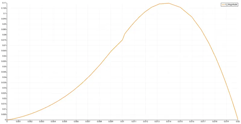
Velocity graph @ x=0.085 from inlet
Case 2:
Mesh
Velocity Contour
Pressure Contour
Velocity graph @ x=0.085 from inlet
Observations:
- The blockMeshDict file of Case 1 is much more easier to setup compared to the Case 2 because of increased number of vertices and blocks
- Velocity and Pressure contours for both the cases are virtually identical. Hence, gridSpacing is not effecting overall flow evolution with time
- The velocity graph at x = 0.085 from the the inlet is smooth for Case 1 while for Case 2 the velocity profile is not smooth in the center of the geometry. This can be explained because of the few and large cell volumes in the center of geometry, which are not sufficient for proper resolution of the flow
Conclusions:
We observe that the gridSpacing has at best no effect on the flow evolution while at worst provide non-smooth velocity profiles. This odd behavior can be explained because of the very small Reynolds number of the flow (Re = 0.1*0.2/0.01 = 2), for which no flow separation near the wall is observed. As a result, we dont require fine cells near the fixedWalls of the domain.
Although in this specific case, gridSpacing provides no advantage, they are extremely important for flows at high Reynolds number.