Week 7 - Mid-term Project - Natural Convection
Circuit Breaker: Effect of Natural convection
Objective: The objective of this challenge is to Verify the temperature rise for the low-voltage control panel for the given configuration. Perform the simulation as per the regulations that have been provided in the challenge.
Problem Description:
- Here we need to verify the temperature rise for the low-voltage control panel.
- For that, build the enclosure with Panel dimensions: height 2000mm, width 1600 mm depth: 700mm. After creating the enclosure, scale the cabinet size also. So that the airflow is also circulated equally.
- The mesh assemblies separately option is used, so that the non-conformal mesh can be obtained.
- Now, solve the problem for natural convection by keeping the radiation surface to surface.
Introduction:
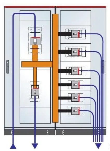
Low voltage control panel:
A low voltage panel is a component of an electrical distribution system that divides an electrical power feed into branch circuits while providing a protective fuse or circuit breaker for each circuit in a common enclosure. In essence, panelboards are used to protect against electrical overloads and short circuits while distributing electricity throughout a building or facility.
Circuit Breaker:
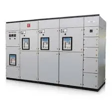
A circuit breaker is an automatically operated electrical switch designed to protect an electric circuit from damage caused by excess current from an overload or short circuit. Its basic function is to interrupt current flow after a fault is detected. Unlike a fuse, which operates once and then must be replaced, a circuit breaker can be reset (either manually or automatically) to resume normal operation.
Circuit breakers are made in varying sizes, from small devices that protect low-current circuits or individual household appliances, up to large switchgear designed to protect high-voltage circuits feeding an entire city. The generic function of a circuit breaker, or fuse, as an automatic means of removing power from a faulty system, is often abbreviated as OCPD (Over Current Protection Device).
Types of circuit breakers are:
- Low-voltage
- Solid-state
- Magnetic-state
- Thermal-magnetic
- Magnetic-Hydraulic, etc.
Geometry:
- Using the Icepak, we have created a geometry of the enclosure with the dimensions of height 2000mm, width 1600 mm depth: 700mm.
- By trial and error, the size of the cabinet is set to the dimensions of 3300 * 3000 * 2400 mm.
- To the panel enclosure, we set a couple of grilles through which the air is passed in rotated inside the enclosure and leave from another grille.
- The natural convection phenomena is likely to happen when the air rotated inside the enclosure while the circuit breakers conducting heat with bus bars.
- The grilles are mounted on the enclosure as downside grille, its flow direction is normal in which is an inlet to the enclosure for air circulation.
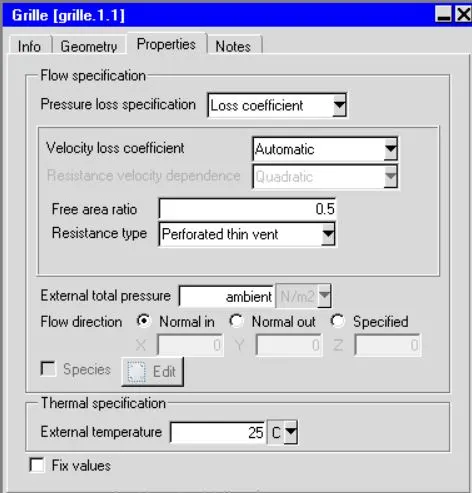
- The upper grille, its flow direction is set to normal out, so the air circulated inside went outside through this grille.
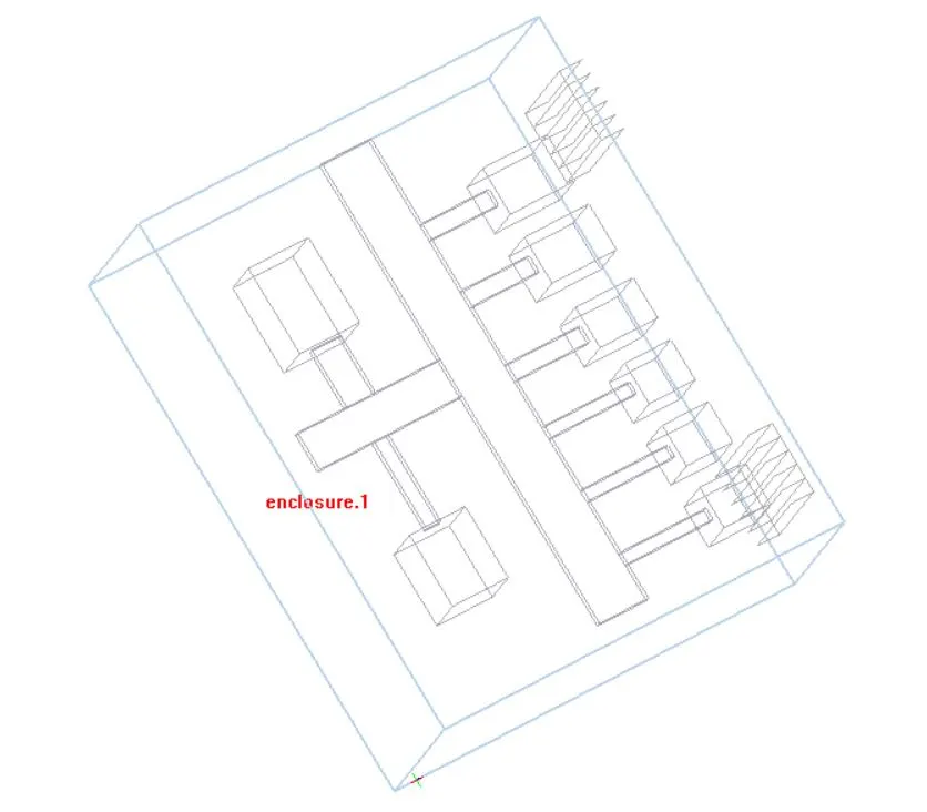
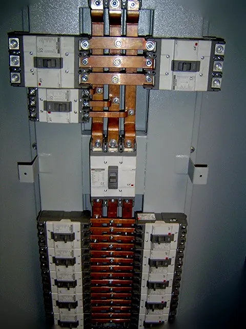
- Here we have created a geometry of an enclosure containing circuit breakers in the form of blocks, and bus bars are connected to them.
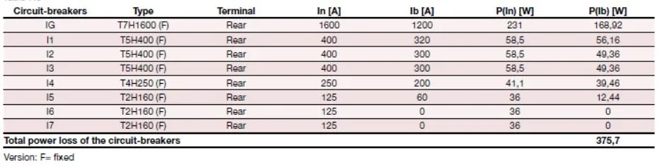
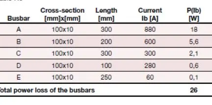
- Dimensions and power in watts for the bus bars, circuit breakers are provided in the challenge.
- Make sure that the bis bars are accurately connected with the circuit breakers without any gap left in between them.
Meshing:
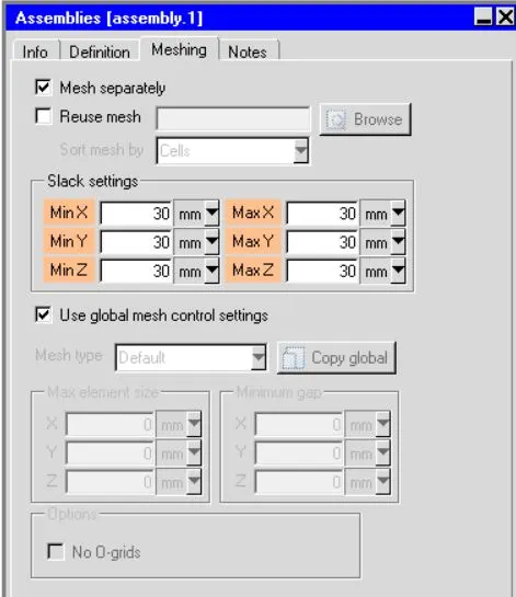
- To obtain the non-conformal meshing, we have toggled the mesh assemblies separately option in the mesh control.
-
A non-conformal mesh, when there are partial or zero matchings of nodes at the interface. This means that one, few, or every node on one side of the interface doesn’t have a match on the other side of the interface.
- Non-conformal interface calculations are handled using a virtual polygon approach, which stores the area vector and centroid of the polygon faces.
-
This approach does not involve node movement and cells are not necessarily water-tight cells. Hence gradients are corrected to take into account the missing face area.
- When the Mesh separately options for an assembly is turned on, the offset added to Assembly in the respective direction is called Slack Values.
-
By default, the slack values are zero in all directions. However, in order to use non-conformal mesh, the slack values should always be a positive number except it can be zero when the non-conformal boundary touches a hollow object or cabinet boundary.
-
The Slack values should be specified in such a way that cells on both sides of the interface are either fluid or solid, with the same material, and it does not violate any of the "Non-Conformal Assembly Rules" given in the attachment.
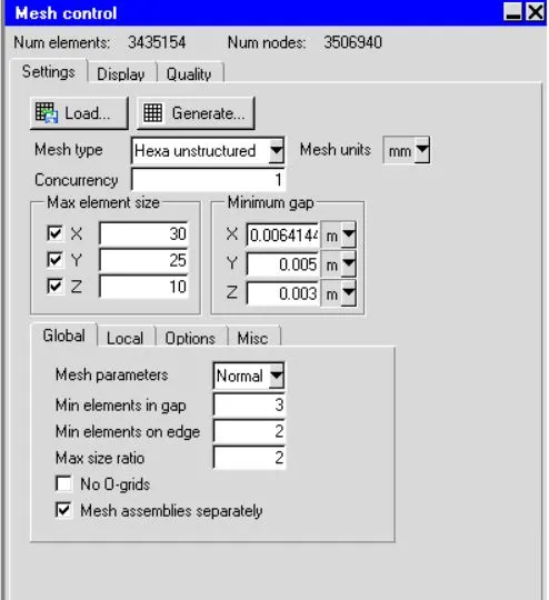
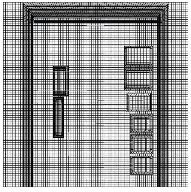
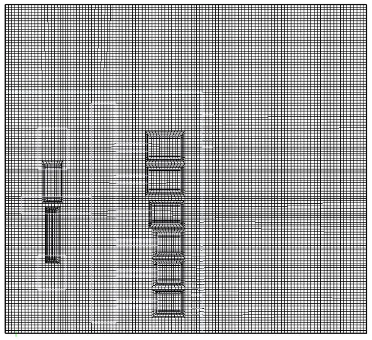
- Here we generate the non-conformal mesh with the slack values, the generated elements are 3435154, and the nodes are 3506940.
- A slack value of 30 mm is used for the assemblies.
- Enclosure mesh
- Cabinet mesh
Skewness:
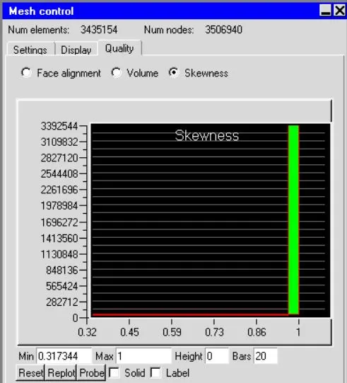
- Skewness is defined as the difference between the shape of the cell and the shape of an equilateral cell of equivalent volume.
- A general rule is that the maximum skewness for a triangular/tetrahedral mesh in most flows should be kept below 0.95, with an average value that is less than 0.33.
- In this case, we achieved a good skewness value regarding the mesh quality.
Numerical setting:
Basic parameters:
- In the basic parameters where we have given whether the solution runs for temperature, flow, and setting up for the initial temperature as well as radiation temperature, etc.
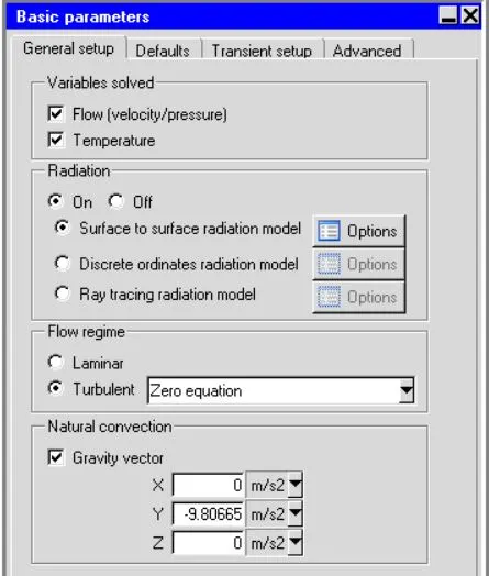
- To capture the natural convection phenomena in the problem, it is necessary to toggle the radiation option and then toggle the surface to surface radiation model.
- A turbulent flow regime has to be calculated with the gravity vector of -9.81 m/s in Y-direction in the natural convection space.
- The initial temperature for the case is set to 25 deg centigrade.
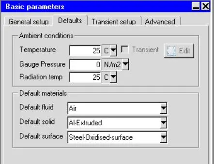
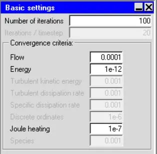
Basic Settings:
- Here in the basic settings panel, we need to give the number of iterations to 100.
- The convergence criteria of Flow is set to 0.0001 and energy is set to 1e-7, turbulent kinetic energy to 0.001, and joule heating is set to 1e-7.
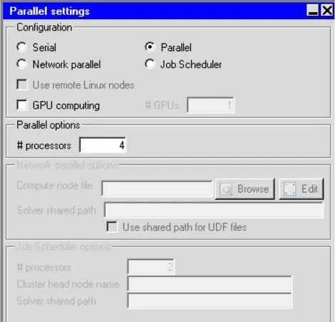
Parallel settings:
- Here I have toggled the parallel option and given the four processors because my PC supports till this point. We can increase or decrease the number of processors as per they are situated in the PC.
Advanced settings:
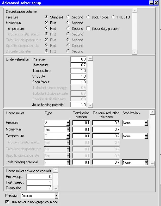
- Here in this panel, we give the inputs as the discretization schemes for the pressure, momentum, and temperature are of the first order.
- The double precision is given. Single precision means that the floating-point numbers will be represented in a 32-bit system whereas double-precision means that they will be represented in a 64-bit system. So Calculation in double precision will be more accurate.
Residual plot:
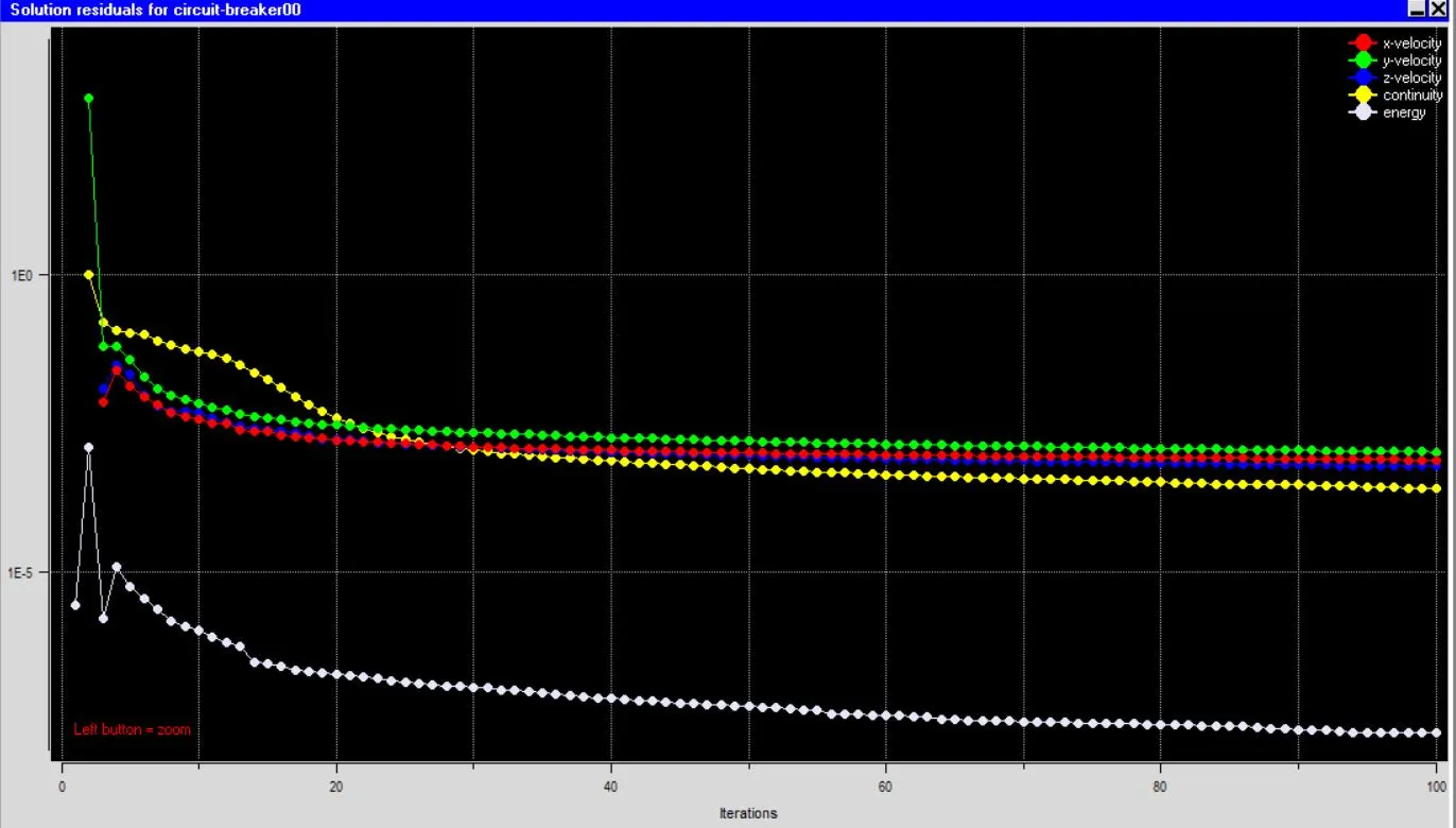
- From the above residual plot, we have seen that the solution gets converged at nearly iteration no.60.
- After iteration no.60, the solution remains the same and we observe no instability in the residual plot.
- At the same time the velocity, continuity, and energy equation are well below the ranges we applied in the basic setting of iterations. Which means the solution gets very well converged.
Examine and post-process the results:
Natural convection inside enclosures:
- Natural convection in enclosures, also known as internal convection, takes place in rooms and buildings, furnaces, and cooling towers, as well as electronic cooling systems.
- Internal natural convection is different from the cases of external convection, where a heated or cooled wall is in contact with the quiescent fluid and the boundary layer can be developed without any restriction.
- Internal convection usually cannot be treated using simple boundary layer theory because the entire fluid in the enclosure engages to the convection.
Temperature:
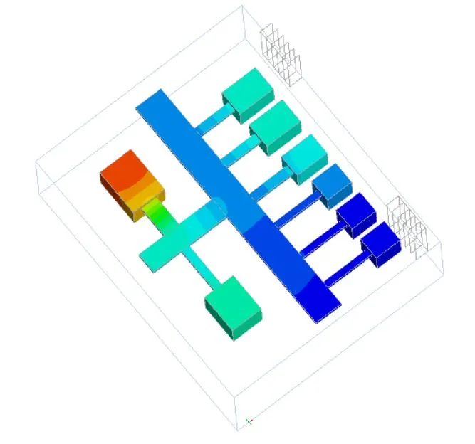
- Filled colors, give a good visualization for the temperature, pressure, and mass flow rate, etc.
- The color legends are used to show the temperature contour.
- Joule heating (also referred to as resistive or ohmic heating) describes the process where the energy of an electric current is converted into heat as it flows through a resistance.
- In particular, when the electric current flows through a solid or liquid with finite conductivity, electric energy is converted to heat through resistive losses in the material.
- The heat is generated on the microscale when the conduction electrons transfer energy to the conductor's atoms by way of collisions.
- Here in the above case also as the electric power is passing through the circuit breakers, as the length of the conductor is increasing, due to the resistance offered by the components, the current-carrying will be less.
- Because of the above statement, the heat flow of components is slightly decreasing while the length of the conductor increases.
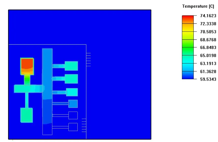
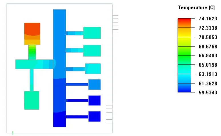
- In the above contour, we have seen that the max. temperature is 74.16 deg and min. the temperature is 59.53 deg.
- The object face of the components gives us a more detailed view compared to the cut plane.
Temperature particle trace animation: https://youtu.be/cQiQvBgSMIU
Velocity:
- As we have created a couple of grilles to the enclosure, the circulation of the air has happened through these grilles only.
- To circulate the air inside of the enclosure we kept the free area ratio to 0.5 a non-dimensional number.
- The natural convection phenomena happen due to the air circulated over the heated bus bars and circuit breakers.
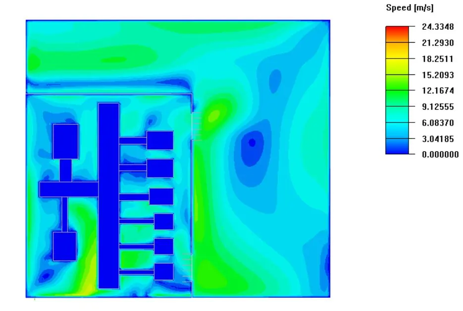
- The velocity in the enclosure is built up to 24 m/s. The max velocity is attained outside of the enclosure. This means inside the cabinet when the flow hits to the enclosure or to the cabinet walls the max. velocity is attained.
- The particle trace will clearly explain to us whether the flow, actually coming from downside grill, and leaving from the upper grill.
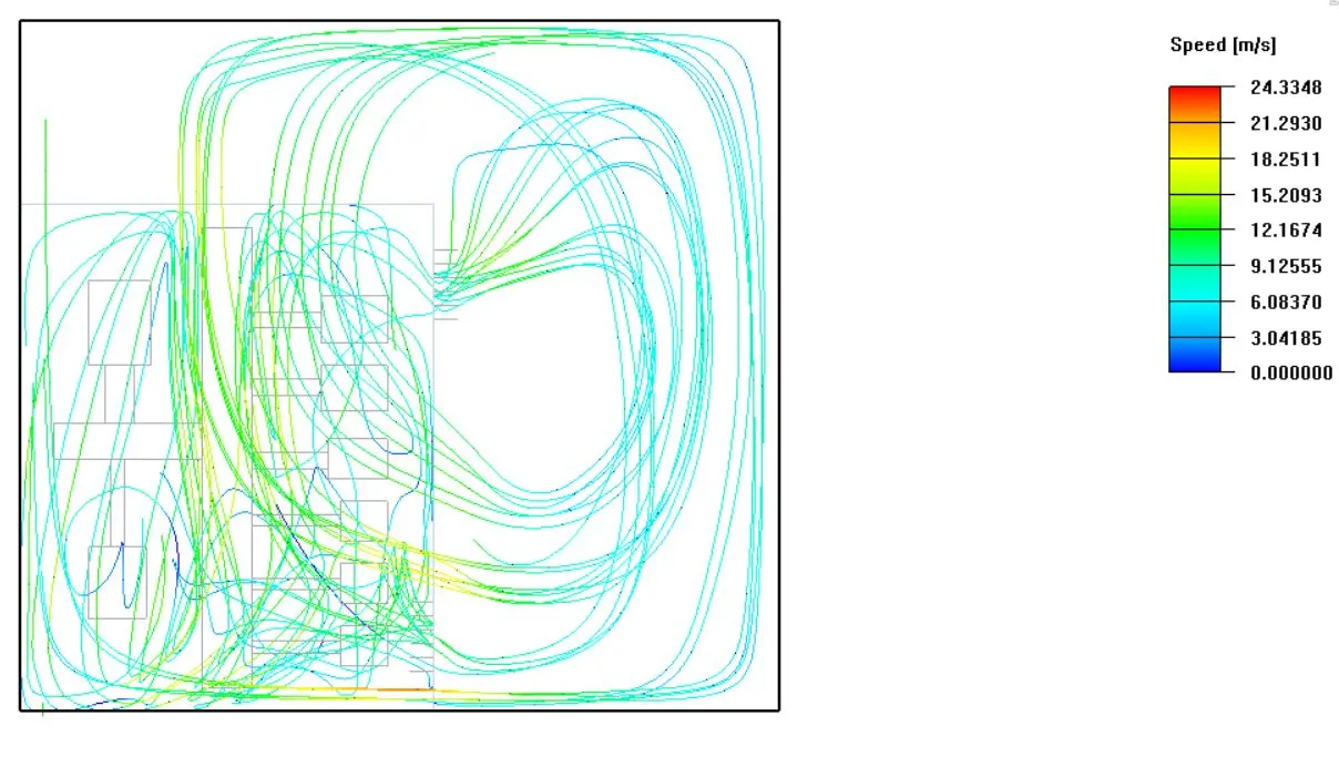
- We can clearly see hear that the flow is coming inside from the downside grill and leaving from the upper grill. This tells us the physics we have set for the problem is correct.
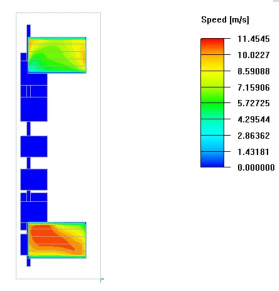
- So, coming to the velocity inside the enclosure, it seems like the max. velocity inside the enclosure is 11.45 m/s.
- The max. the velocity of the enclosure is also recorded at the entry.
Speed particle trace animation: https://youtu.be/wDssZw-xcsw
Summary report:
- A summary report is a short, written communication that may have a variety of purposes, such as: To brief the reader on the details of a particular event. To analyze a particular issue, draw conclusions, and make recommendations.
- Go to report -> summary report -> Select the object -> select the value (temp, speed, heaty flow, etc.) -> Write.
Temperature:
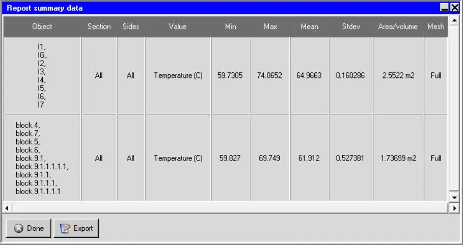
- It gives us the max and min. temperatures of the objects we have selected collectively.
- Here we can also get the mean temperature, standard deviation, and Area/Volume ratio data that can be used to compare the results.
Velocity:
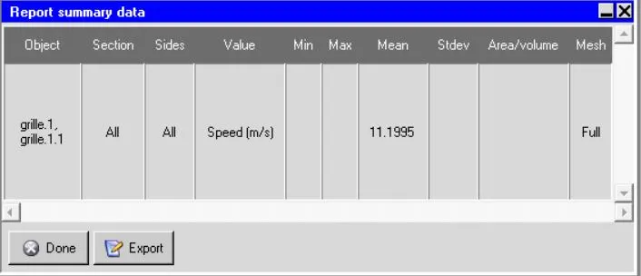
- Above in the velocity section, we have discussed that the max. the velocity of the enclosure is 11.45 m/s. We can conclude that by seeing here mean. temp.
Heat Flow:
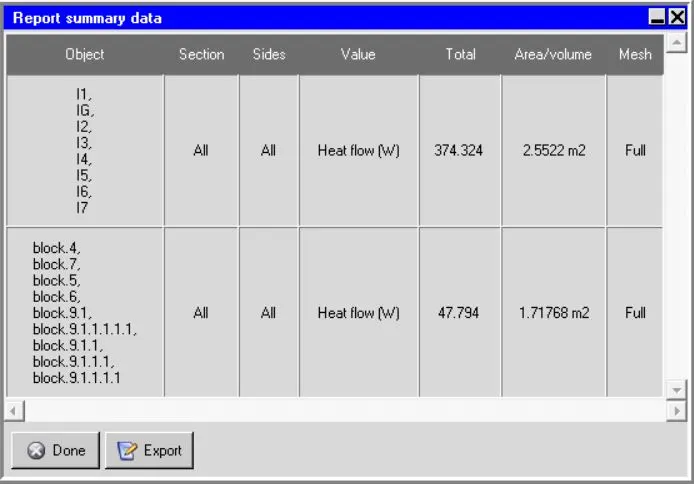
- Heat can flow from one place to another, like all kinds of energy. Heat flows in solids by conduction, where two objects in contact with each other transfer heat between them.
- That happens because the molecules hit each other, and the faster-moving molecules in the hot object spread that energy into the cooler object.
- Here if we see the total heat loss or heat flow of the circuit breakers, it is 375.7 W manually (means the input), coming to the simulation it is 374.324 W. Which is matched up to 99%.
- This can be another proof that our simulation is gets converged and throws the correct values as outputs.
Heat transfer coefficient:
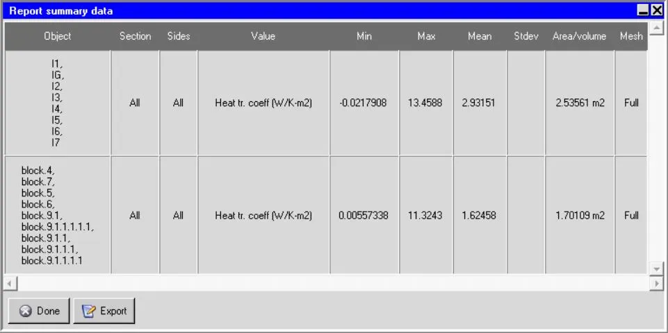
- It is used in calculating heat transfer, typically by convection. The heat transfer coefficient has SI units in watts per squared meter kelvin: W/(m2K).
- The heat transfer coefficient is the heat transferred per unit area per kelvin.
- Thus the area is included in the equation as it represents the area over which the transfer of heat takes place. The areas for each flow will be different as they represent the contact area for each fluid side.
- The negative gradient in min. heat tr. coeff of circuit breakers represents: In case of constant wall temperature, using adiabatic wall temperature as reference temperature can result in a negative heat transfer coefficient, which means the heat flux has a different direction with the defined driving temperature difference.