Week 7 - Mid-term Project - Natural Convection
Mid-Term Project - Natural Convection
Aim:
The objective of this challenge is to authenticate the increase in temperature for the low voltage control panel for the configuration in a statement. Perform a simulation in accordance with the regulations provided for in the challenge.
Objective:
Here we need to evaluate the increase in temperature of the low voltage control panel.
Build the enclosure with the dimensions of the panel:
height 2000mm
width 1600 mm
depth 700mm
After designing the frame, always measure the size of the cabinet. So that the flow always circulates similarly
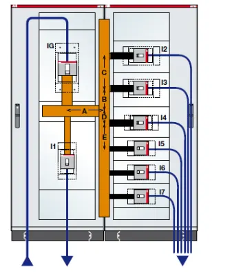
Theory
Low voltage control panel:
A low voltage panel is a component of an electrical distribution system that divides an electrical power supply into an electrical circuit while providing a protective fuse or circuit breaker for each circuit in a common enclosure.
A low-voltage network or secondary network is a part of electric power distribution that carries electric energy from distribution transformers to electricity meters of end customers. Secondary networks are operated at a low voltage level, which is typically equal to the mains voltage of electric appliances.
Electric power distribution systems are designed to serve their customers with reliable and high-quality power. The most common distribution system consists of simple radial circuits (feeders) that can be overhead, underground, or a combination. From the distribution substation, feeders carry the power to the end customers, forming the medium -voltage or primary network, operated at a medium voltage level, typically 5–35 kV. Feeders range in length from a few kilometers to several tens of kilometers. As they must supply all customers in the designated distribution area, they often curve and branch along the assigned corridors. A substation typically supplies 3–30 feeders. Distribution transformers or secondary transformers, placed along with feeders, convert the voltage from the medium to a low voltage level, suitable for direct consumption by end customers mains voltages. Typically, rural primary feeder supplies up to 50 distribution transformers, spread over a wide region, but the figure significantly varies depending on the configuration. They are sited on pole tops, cellars, or designated small plots. From these transformers, low-voltage or secondary network branches off to the customer connections at customer premises, equipped with electricity meters.
CIRCUIT BREAKER :
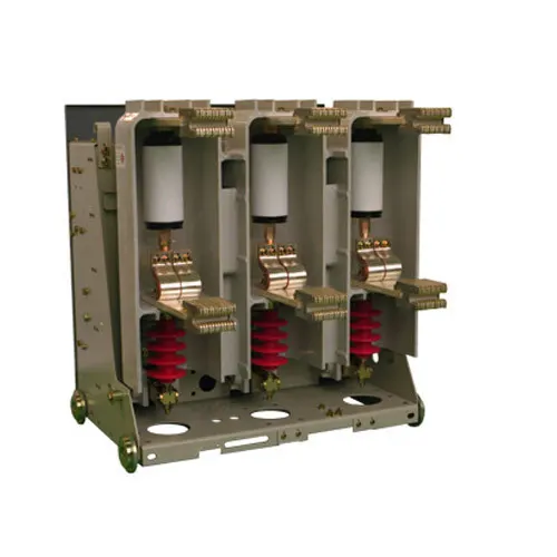
The circuit breaker is an electronic device that is continuously maintained to secure the electrical circuit from interference generated by excess current from an overload or short circuit. The basic purpose is to terminate the current flow whenever a fault has been detected. In comparison to a fuse that works once and then needs to be repaired, the circuit breaker may be reset (either manually or automatically) to restore regular service.
Circuit breakers are made in varying sizes, from small devices that protect low-current circuits or individual household appliances, up to large switchgear designed to protect high voltage circuits feeding an entire city. The generic function of a circuit breaker or fuse as an automatic means of removing power from a faulty system is often abbreviated as OCPD (Over Current Protection Device).
Types of circuit breakers are:
- Low-voltage
- Solid-state
- Magnetic-state
- Thermal-magnetic
- Magnetic-Hydraulic, etc.
Geometry :
Using the Icepak, we have created a geometry of the enclosure with the dimensions of
Height 2000mm
Width 1600 mm
Depth: 700mm.
By trial and error, the size of the cabinet is set to the dimensions of 3300 * 3000 * 2400 mm.
For the panel enclosure, we put a few grids from which the air flows in rotated within in the enclosure and leaving another grid.
Natural convection effects are likely to arise as the air axis of rotation within the enclosure as the circuit breakers heat up the bus bars. The grids are placed on the enclosure as a downside system, with such a normal flow direction in which the air circulation enclosure is the inlet.
Grill on the Top of the surface:
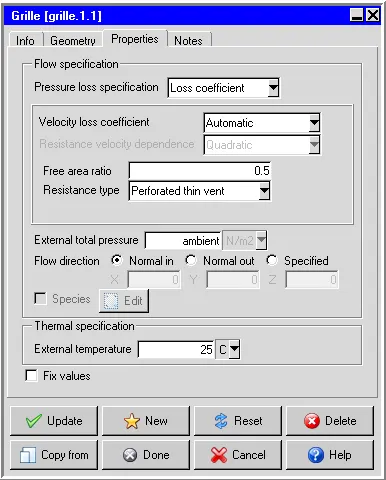
The upper grille its flow direction is set to normal out so that air circulated inside went outside through this grille.
Grill on the Bottom of the surface:
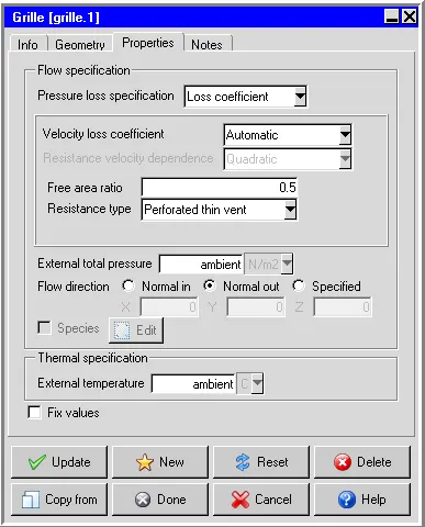
The Lower grille is set in the direction of the in-flow.
The geometry :
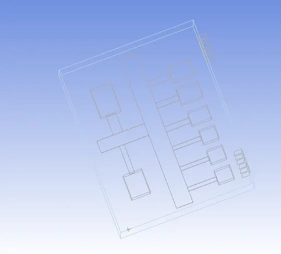
Here we have built an enclosure configuration that includes circuit breakers in the form of frames, and bus bars are attached to them. Measurements and control in watts for bus bars, circuit breakers are also included in the challenge. Make sure that the bis bars are probably exactly connected to the circuit breakers without any gap left between them.
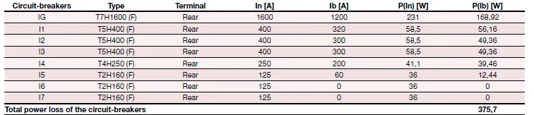
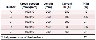
Busbar :
Meshing:
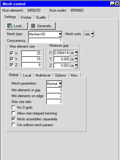
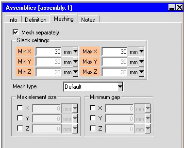
- Here we generate the non-conformal mesh with the slack values, the generated elements are 8458293, and nodes are 8589882.
- A slack value of 30 mm is used for the assemblies.
Mesh for the cabinet:
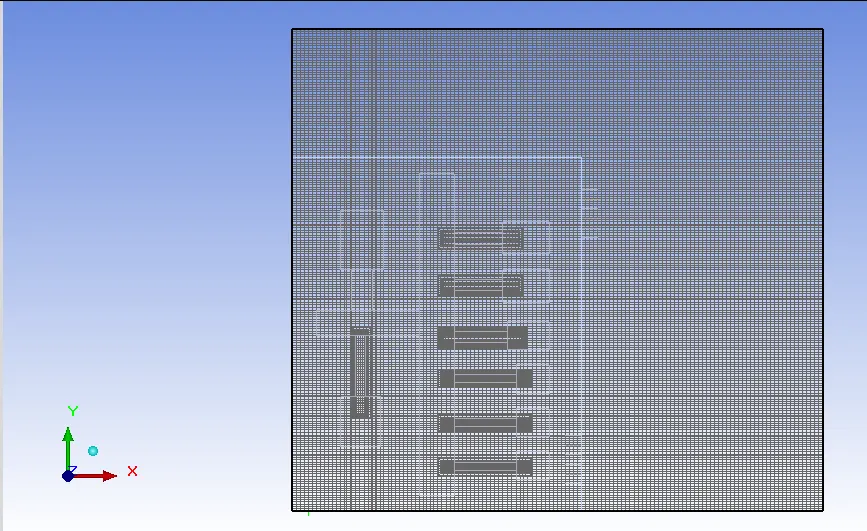
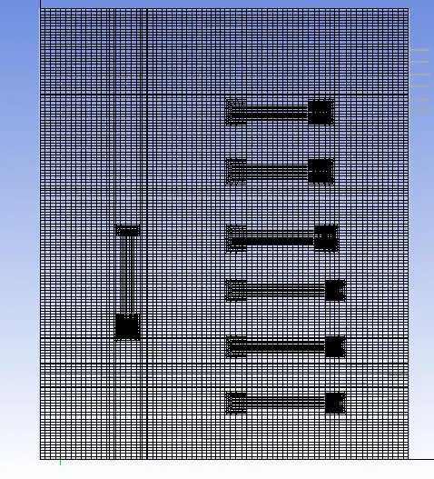
Mesh for the Enclosure:
Skewness:
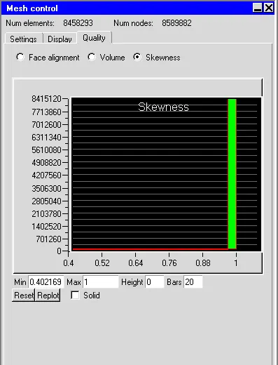
- A general rule is that the maximum skewness for a triangular/tetrahedral mesh in most flows should be kept below 0.95, with an average value that is less than 0.33.
- In this case, we achieved a good skewness value regarding the mesh quality.
Setup:
Basic parameters: Flow & Radiation is on
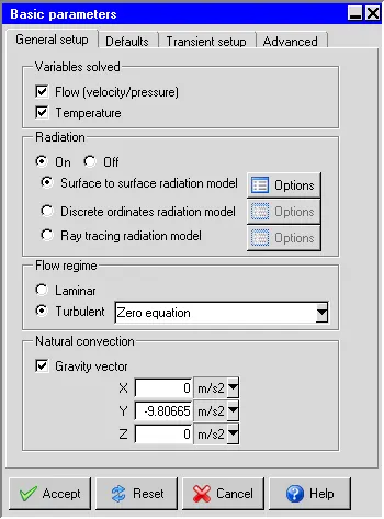
- To capture the natural convection phenomena in the problem, it necessary to toggle the radiation option and then toggle surface to surface radiation model.
- A turbulent flow regime has to be calculated with the gravity vector of -9.81 m/s in Y-direction in the natural convection space.
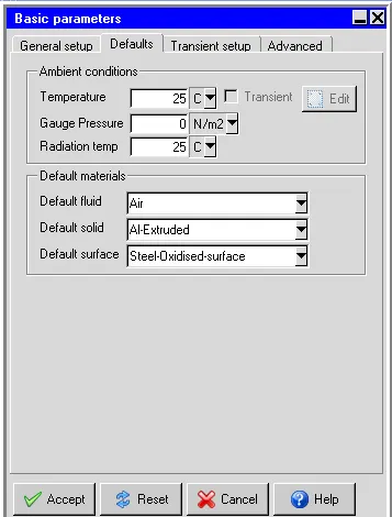
- The initial temperature for the case is set to 25 deg centigrade
Basic settings:
Set no of iterations 100 and convergence criteria for energy to 1e-12.
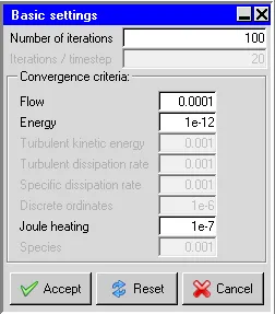
The total number of iteration was set to be 100 iterations and coming to the convergence criteria the flow was set to 0.0001 and energy was 1e-12, and the turbulent kinetic energy and turbulent dissipation rate were 0.001
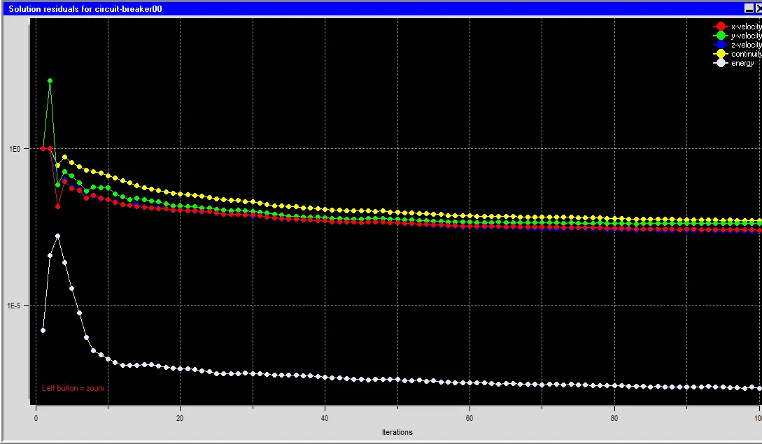
From the residual plot, it is clear that the simulation has reached the converged stage and also obtained the converge, and they are no fluctuations in the plot.
Parallel settings:
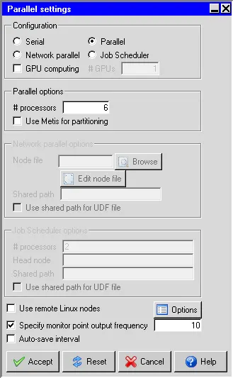
Here we have to use the parallel option and given the six processors because my PC supports till this point. We can increase or decrease the number of processors as per they are suitable in the PC.
Temperature Linear solver: F cycle is selected for Type Enter 1e-6 for both the Termination criterion and Residual reduction tolerance
The discretization scheme properties were set accordingly as shown below
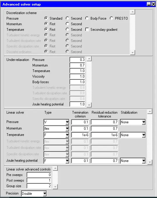
Enter a value of 1e-6 for both the Termination criterion and Residual reduction tolerance and the F cycle is was selected.
Select Double for the solver Precision.
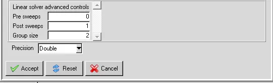
Save and Solve the model.
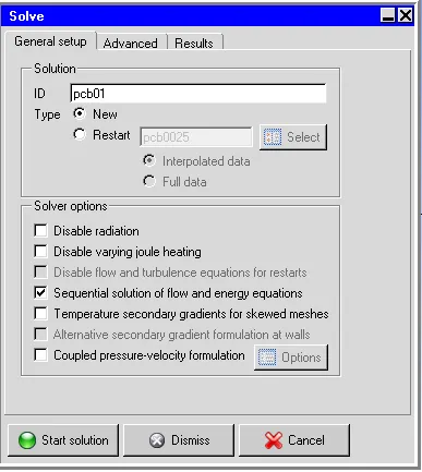
There are no universal metrics for judging convergence, a good indicator is when the solution no longer changes with more iterations, and when the residuals have decreased to a certain degree. The default criterion is that each residual will be reduced to a value of less than 10^-3 except the energy residual, for which the default criterion is 10^-7. It is a good idea to judge convergence not only by examining residuals levels but also by monitoring relevant integrated quantities.
Post-processing and results:
Temperature contour:
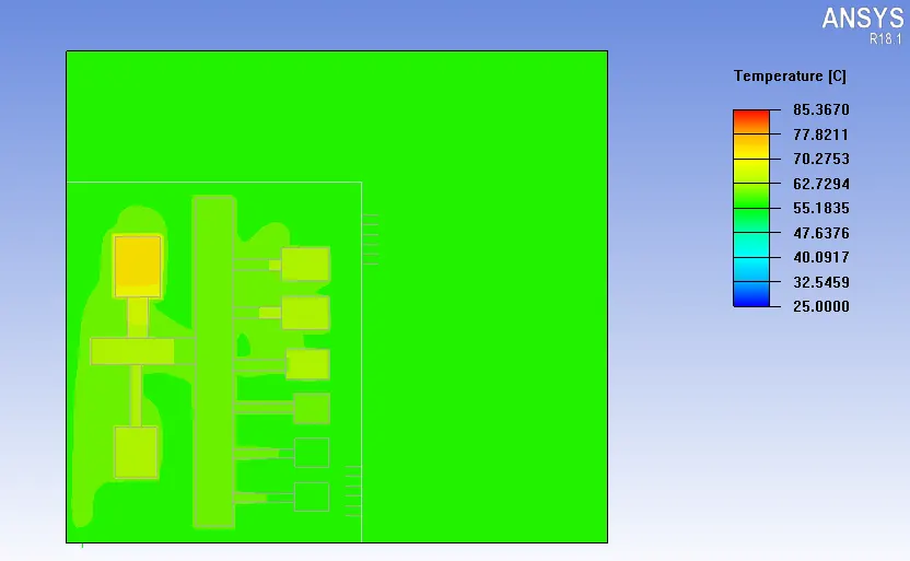
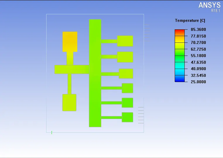
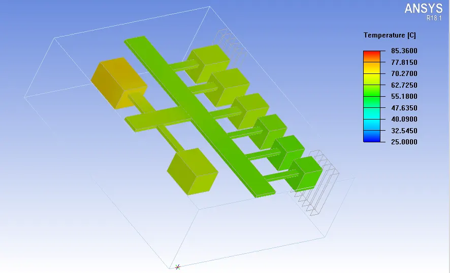
- In the above contour, we have seen that the max. The temperature is 85.36 deg and min. the temperature is 25.00 deg.
- The object face of the components gives us a more detailed view compare to the cut plane.
Velocity:
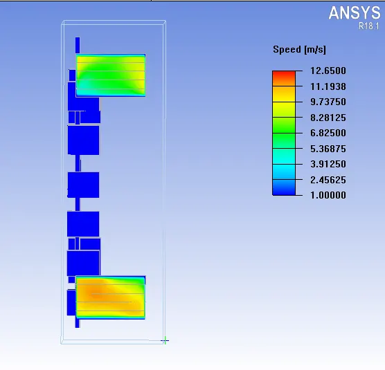
- As we have created a couple of grilles to the enclosure, the circulation of the air has happened through these grilles only.
- To circulate the air inside of the enclosure we kept the free area ratio to 0.5 a non-dimensional number.
- The natural convection phenomena happen due to the air circulated over the heated bus bars and circuit breakers
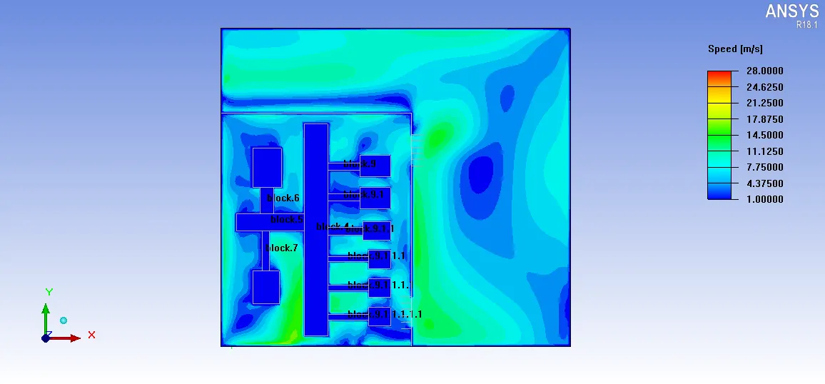
- The velocity in the enclosure is built up to 28 m/s. The max velocity is attained outside of the enclosure. This means inside the cabinet when the flow hits to the enclosure or to the cabinet walls the max. velocity is attained.
- The particle trace will clearly explain to us whether the flow, actually coming from downside grill, and leaving from the upper grill.
- We can clearly see hear that the flow is coming inside from the downside grill and leaving from the upper grill. This tells us the physics we have set for the problem is correct.
- So, coming to the velocity inside the enclosure, it seems like the max. velocity inside the enclosure is 12.65 m/s.
- The max. velocity of the enclosure is also recorded at the entry
Summary report:
- A summary report is a short, written communication that may have a variety of purposes, such as: To brief the reader on the details of a particular event. To analyze a particular issue, draw conclusions, and make recommendations.
- Go to report -> summary report -> Select the object -> select the value (temp, speed, heaty flow, etc.) -> Write.
Temperature:
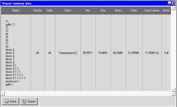
- It gives us the maximum and minimum temperatures of the collectively chosen objects. The mean temperature, standard difference, and area/volume ratio data can also be used for comparison of the results.
Velocity:
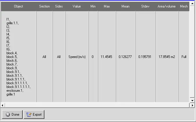
Above in the velocity section, we discussed the max. The enclosure velocity is 11.4545 m/s. We can conclude that it means seeing here.
Heat Flow:
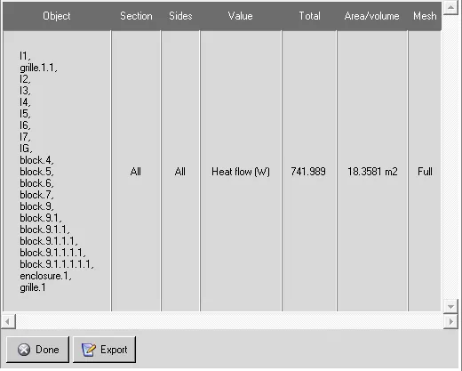
- Here if we see the total heat loss or heat flow of the objects, it is 741.989W. This can be another proof that our simulation is gets converged and throws the correct values as outputs.
Heat transfer coefficient:
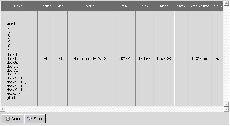
- Circuit breaker coefficient represents: if the wall's temperature is constant, the use of adiabatic wall temperature can lead to a negative heat transfer coefficient, meaning that the heat flux has a different direction with a defined temperature difference.
Conclusion:
From this challenge, we can conclude that there is an increase in temperature for the low voltage control panel for the configuration in a statement.