Week-7 Head Impact
OBJECTIVE
To create a simulation of a pedestrian head impact and calculate the Head Impact Criterion (HIC) for each of the following cases.
- Simple head model impacting against a rigid wall.
- Child head dummy model impacting against a rigid wall.
- Child head dummy model impacting against the hood.
INTRODUCTION
The head injury criterion (HIC) is a measure of the likelihood of head injury arising from an impact. The HIC can be used to assess safety related to vehicles, personal protective gear, and sport equipment.
Normally the variable is derived from the measurements of an accelerometer mounted at the center of mass of a crash test dummy’s head when the dummy is exposed to crash forces.
It is defined as:

where t1 and t2 are the initial and final times (in seconds) chosen to maximize HIC, and acceleration a is measured in gs (standard gravity acceleration).
This means that the HIC includes the effects of head acceleration and the duration of the acceleration. Large accelerations may be tolerated for very short times.
For example, at a HIC of 1000, there is an 18% probability of a severe head injury, a 55% probability of a serious injury, and a 90% probability of a moderate head injury to the average adult.
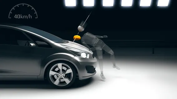
The bumper typically strikes the lower limbs, while the bonnet leading edge strikes in the region of the hip, and head impact subsequently occur on with either the bonnet top or the windscreen area
In this project, a children's head model is provided. An impact simulation is created to replicate a scenario where this head will impact on a car bonnet.
MODEL IMAGES
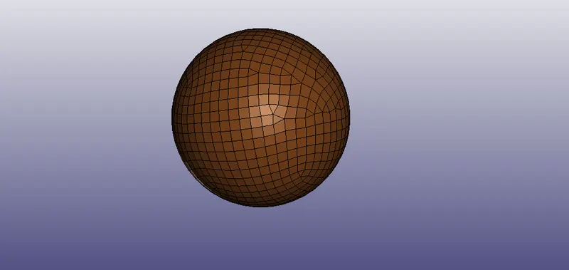
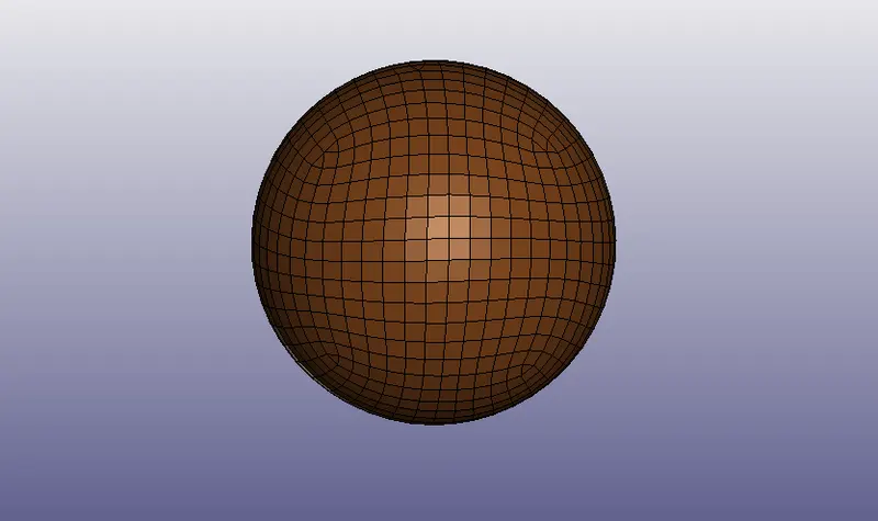
1. Simple head model-
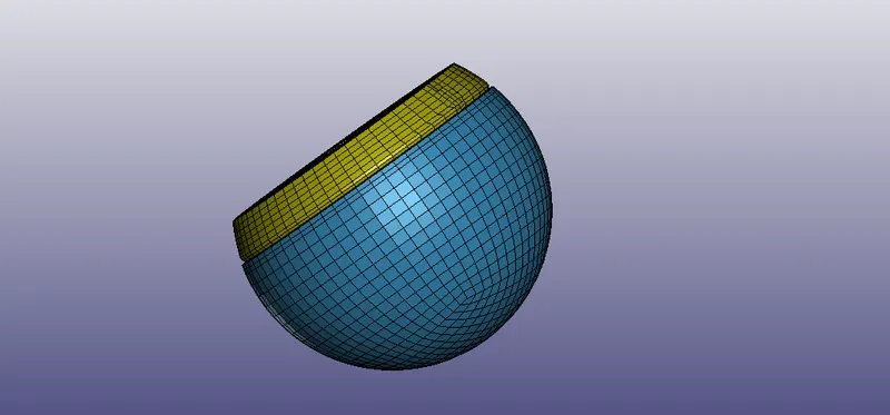
2. Simple child head model-
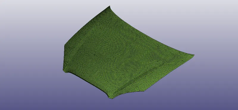
3. Meshed hood-
PROCEDURE
Case 1: Simple head model impacting against rigid wall:
1. Firstly, on LS PrePost, the .k file containing the FE model is imported via File > Import > LS-DYNA keyword file.
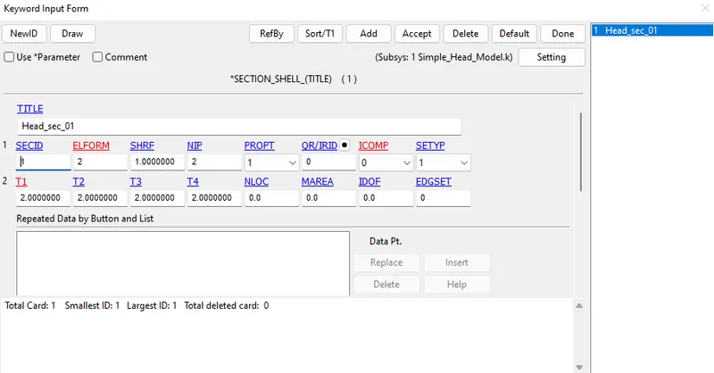
2. The part contains shell elements and we are to assign thickness to it. So, we can access the keyword manager again, select the 'all' option, scroll to SECTION and select SHELL under it. The SHELL section will be used to define the model. We can assign a section ID with ELFORM 2 and a thickness of 2 mm.
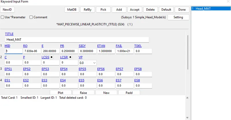
3. Similarly, to create a material, we can go to the keyword manager again, select 'all', and scroll down to the MAT card, under which we can select the 024-PIECEWISE_LINEAR_PLASTICITY. This card is used to define the material. We can assign the material ID (MID), density (RO), Young's Modulus (E), and Poisson's Ratio (PR) here (as of steel in this case). Once we are done, we can click 'accept'. (Here, I have also defined SIGY (Yield stress) and ETAN (Tangent Modulus)).
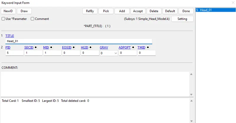
Now, we can go back to the part card and assign the MID and SECID.
4. Moving on, we can now define the boundary conditions.
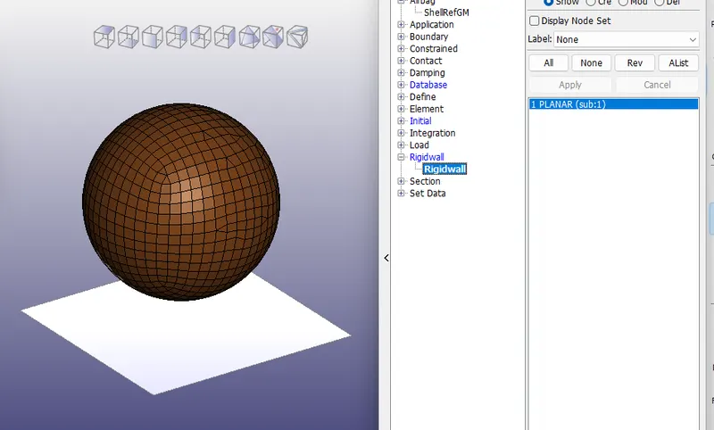
A rigid wall is created at a distance of 30 mm in the x-direction of the simple head model.
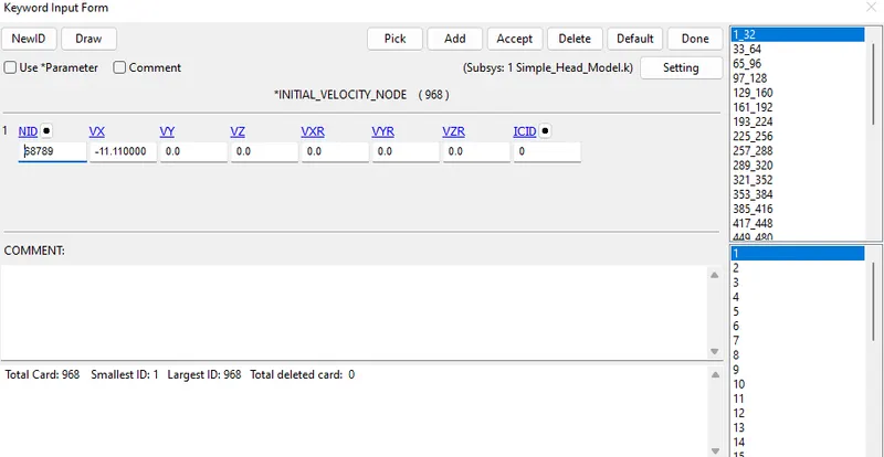
The simple head model is assumed to be impacting the rigid wall at a velocity of 40 kmph i.e. 11.11 mm/ms in the positive x-direction towards rigid wall.
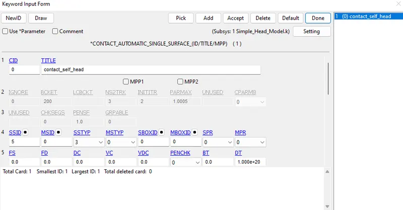
5. Moving on, we need to define the self-contact for the given model. To do so, we can go back to the keyword manager, choose to show all keywords, go to the CONTACT keyword and select AUTOMATIC_SINGLE_SURFACE. Here, we just need to define the slave of this contact property using the part ID (which would be the simple head part). In addition to naming the contact and assigning a CID (contact ID), we needn't worry about anything else here. We can click 'accept' and then 'done'.
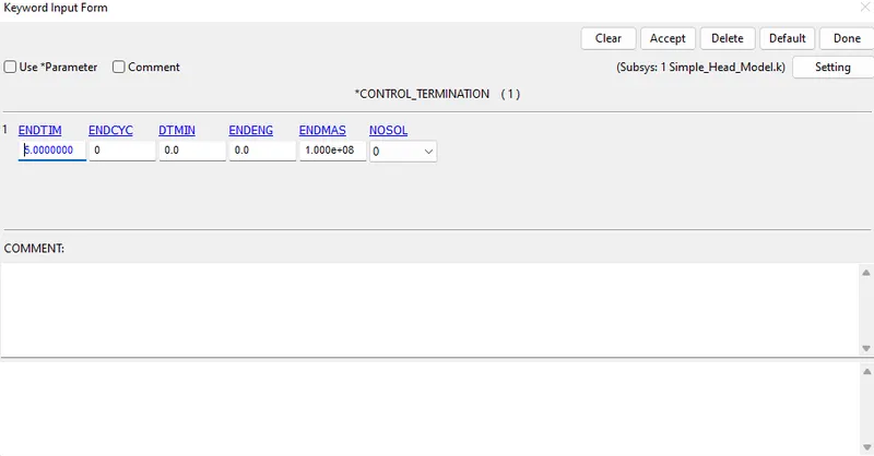
6. Next, we can create a CONTROL card to specify the end time of the simulation. This can be assigned via the TERMINATION card option under the CONTROL keyword in the complete list of keywords in the keyword manager. We can assign a value of 10ms to capture the entire simulation.
7. Finally, we can assign a couple of DATABASE keyword cards for the outputs - namely ASCII_option and BINARY_D3PLOT with a DT (Time interval between outputs) of 0.1ms. The GLSTAT, MATSUM and RWFORC attributes are selected under ASCII_option.
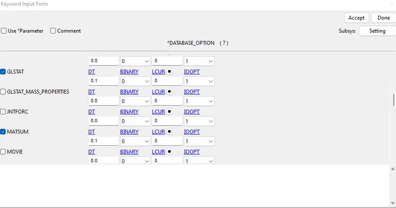
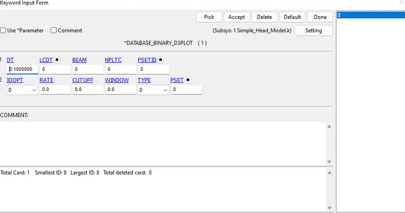
DATABASE_EXTENT_BINARY card with STRFLG =1, is used to compute the elastic strain in the model.
DATABASE_HISTORY_NODE card is used to compute the HIC value of node 69048 in the model.
Once done, we can save it as a .k file and solve it using LS-RUN. The keyword file is inserted and we can click the play button to run the simulation. The number of cores to be utilized can be changed if needed.
Once it is finished without errors (aka Normal Termination), we can reopen LS-Prepost to view the results.
RESULTS-1
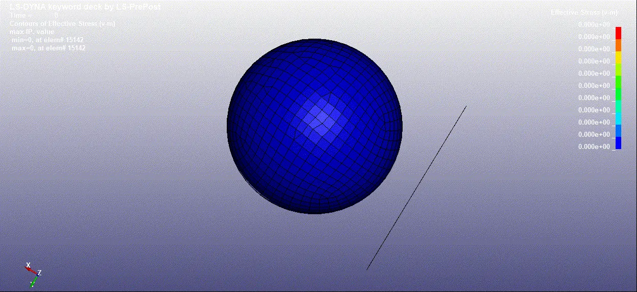
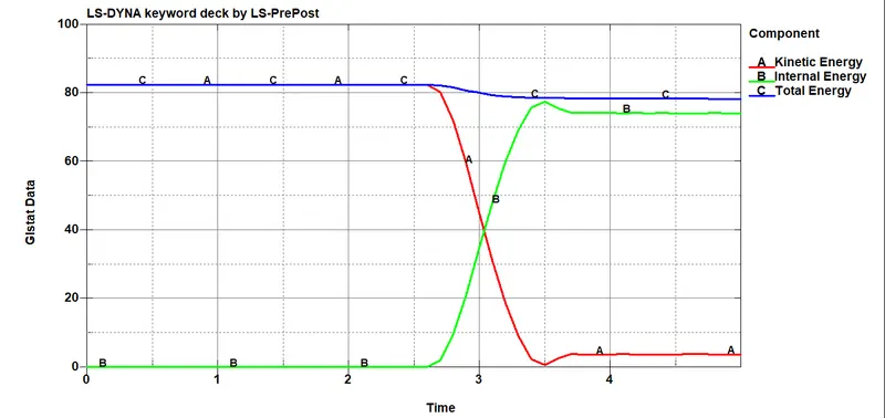
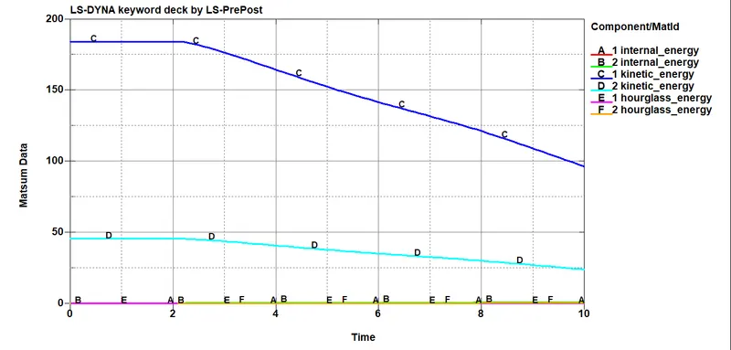
Energy plots-
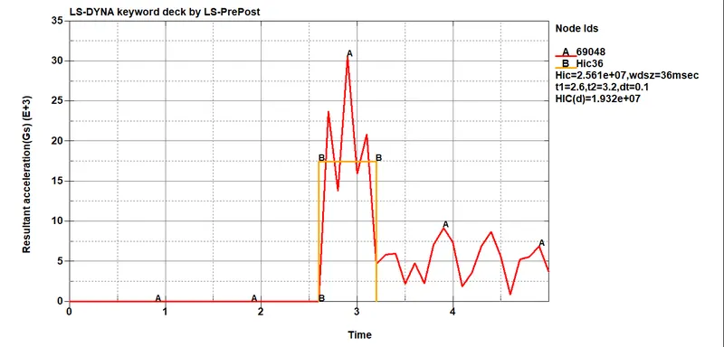
HIC-
Case 2: Child head dummy model impacting against the rigid wall:
1. To simulate a somewhat realistic representation of a child's head impacting a car hood, the provided child head model has to be rotated about 500 along the Y-axis. This is done by using *DEFINE_TRASFORMATION and *INCLUDE_TRANSFORM as shown:
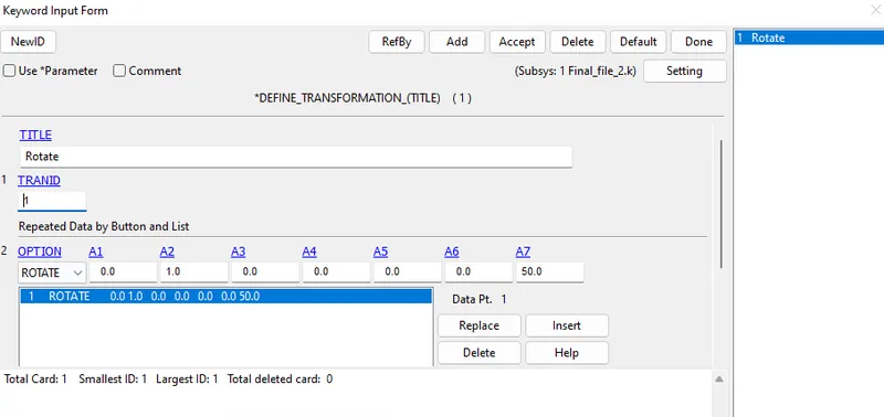
Using DEFINE_TRANSFORMATION card with TRANID=1, the dummy headform model is rotated by OPTION>ROTATE along Y-axis (A2=1) by 500 (A7=50).
Then, the INCLUDE_TRANSFORM card is used to summon the rotated head model file to the main file. The main file is saved with ‘.k’ extension.
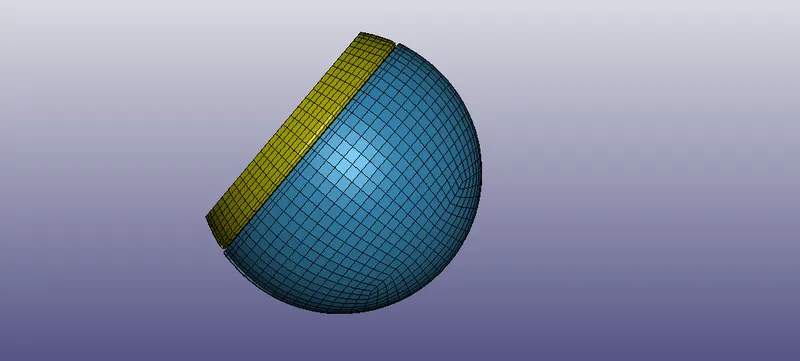
The main file is then opened in LS-PrePost to add the required keywords to complete the simulation deck.
Note: While adding keywords to main file, it needs to be ensure that the subsystem of the keywords is set to that of the main file.
2. Moving on to boundary conditions, we can apply the initial velocity to the headform. Since it is at an angle, the velocity is broken down into two directional components as shown:
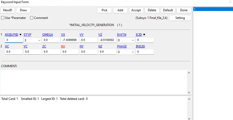
The initial velocity is taken as 40 kmph i.e, 11.11 mm/ms at an angle of 50°. The horizontal and vertical components of the velocities are -7.14 mm/ms and -8.51 mm/ms respectively.
A rigid wall is created at a distance of about 80 mm from the bottom of the standard dummy head model:
3. Just as in the previous case we can create a self-contact card for the head. The same termination time and database options are selected as well. The only difference is the DATABASE_HISTORY_NODE card, which is used to compute the HIC value of node 25679 in the model.
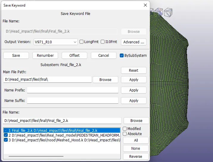
4. The keyword file is saved to the main file using the ‘save keyword as’ option as shown.
Once done, we can save the main file as a .k file and solve it using LS-RUN. The keyword file is inserted and we can click the play button to run the simulation. The number of cores to be utilized can be changed if needed.
Once it is finished without errors (aka Normal Termination), we can reopen LS-Prepost to view the results.
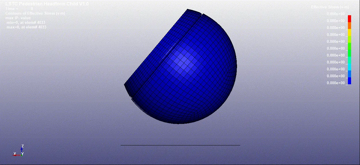
RESULTS-2
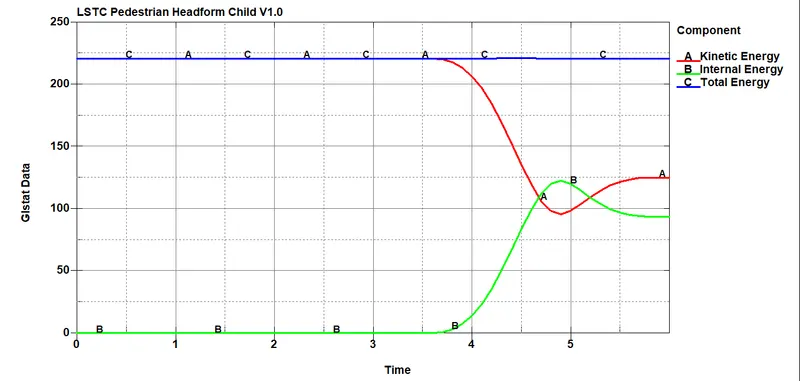
Energy plots-
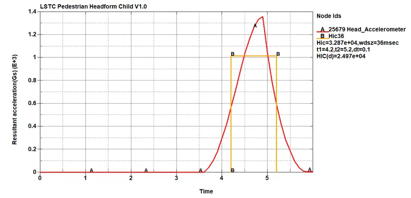
HIC-
Case 3: Child headform dummy model impacting against hood:
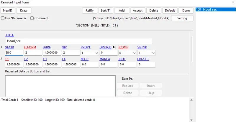
1. After importing the provided meshed hood model, we can define the section property for it. The following section card is applied:
2. MAT24 (Piecewise linear plasticity) card is applied for the material of the hood. Aluminium material properties are assigned to the hood.

3. The keyword file of hood is saved using ‘.k’ extension. The keyword file of hood is pulled into main file using keywords *INCLUDE (just like in the previous case). The child headform is pulled into main file by using *DEFINE_TRASFORMATION and *INCLUDE_TRANSFORM which is similar to what was done in case 2.
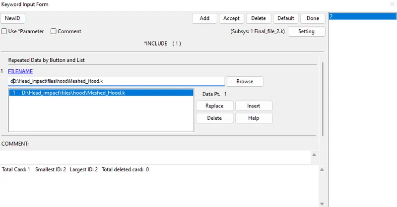
The main keyword file is opened in LS-PrePost and the remaining boundary conditions are added.
4. The initial velocity just as in the previous case is applied.
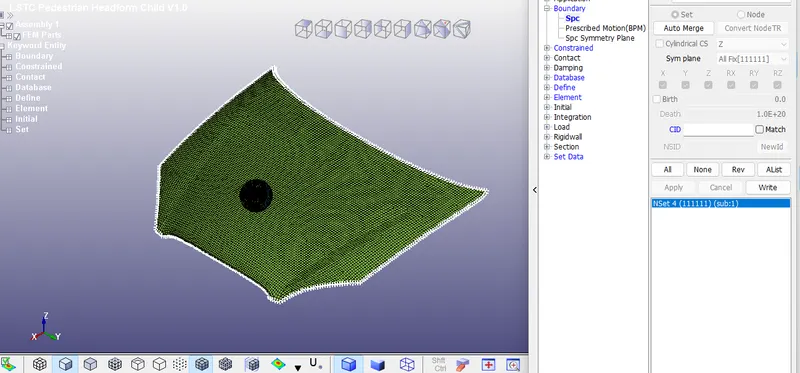
Additionally, the nodes on the edges of the hood are constrained using SPCs. The nodes are constrained in all directions.
5. Also, contact card is assigned. We shall be using AUTOMATIC_SURFACE_TO_SURFACE here since the contact between the headform and the hood is to be defined.
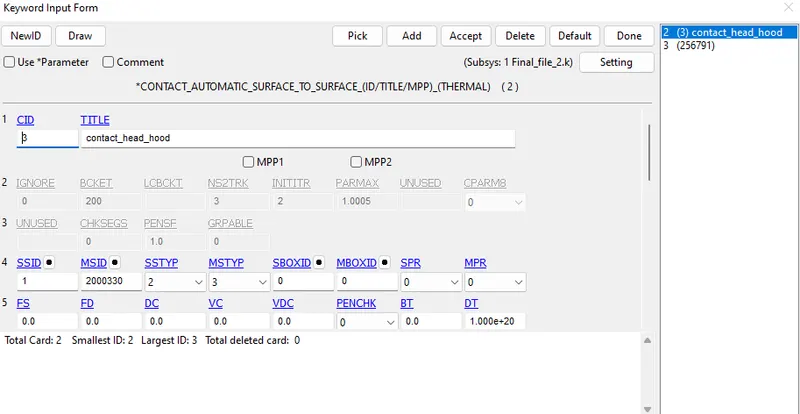
The head model is taken as the slave and the hood as the master.
Additionally, self-contact is defined for the head:
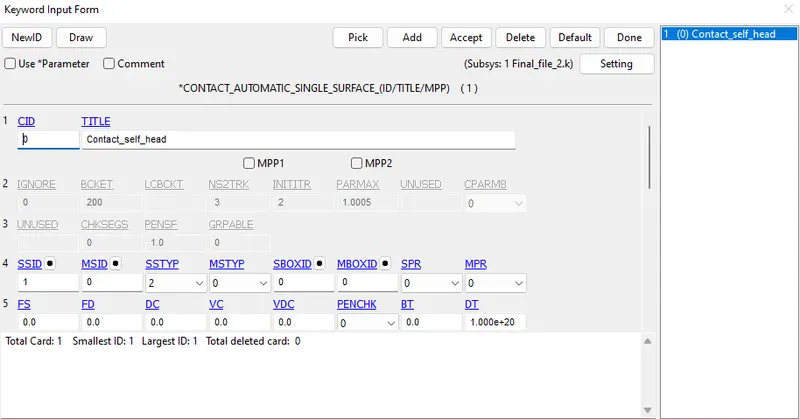
6. The control card and database cards are the same as that of the case (2) scenario.
7. Once done, we can save the main file as a .k file and solve it using LS-RUN. The keyword file is inserted and we can click the play button to run the simulation. The number of cores to be utilized can be changed if needed.
7. Once done, we can save the main file as a .k file and solve it using LS-RUN. The keyword file is inserted and we can click the play button to run the simulation. The number of cores to be utilised can be changed if needed.
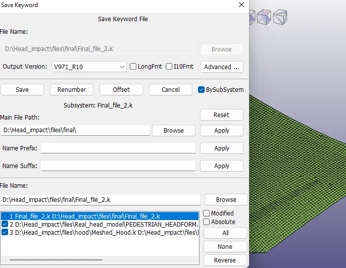
Once it is finished without errors (aka Normal Termination), we can reopen LS-Prepost to view the results.
RESULTS-3
stress-
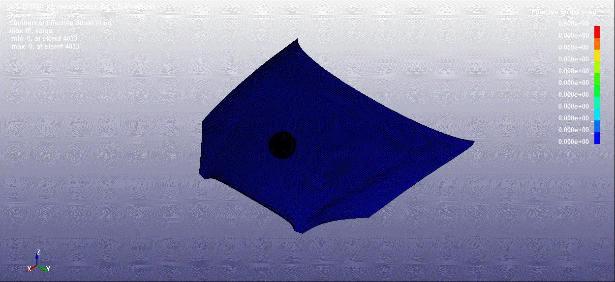
Strain-
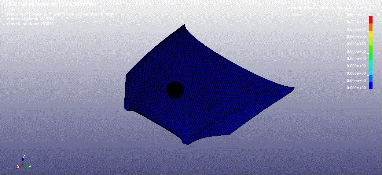
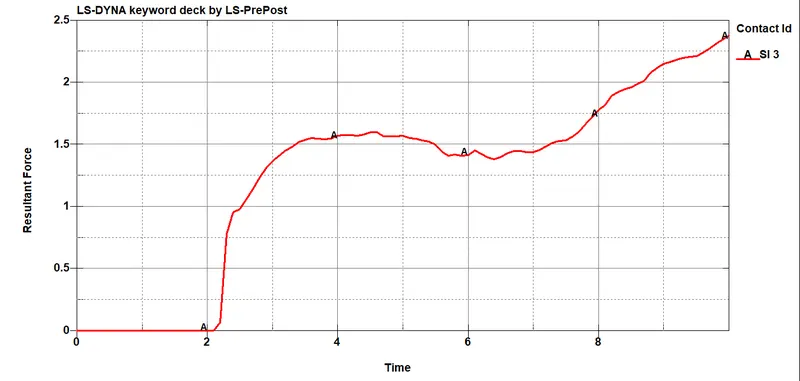
Energy Plots-
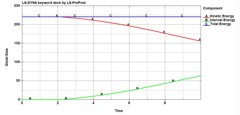
Matsum Data for Hood-
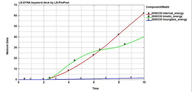
Matsum Data for Head skin and skull-
Contact force between Head and hood-
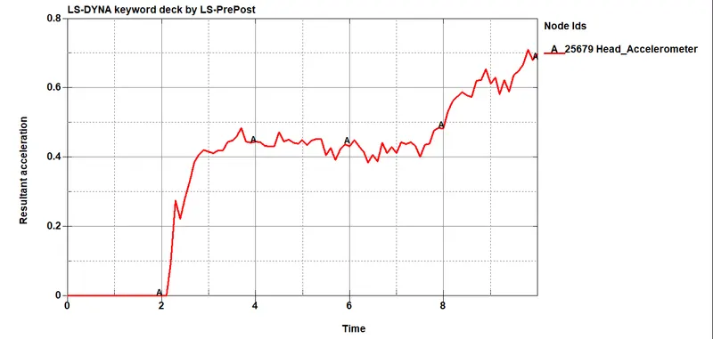
Resultant acceleration-
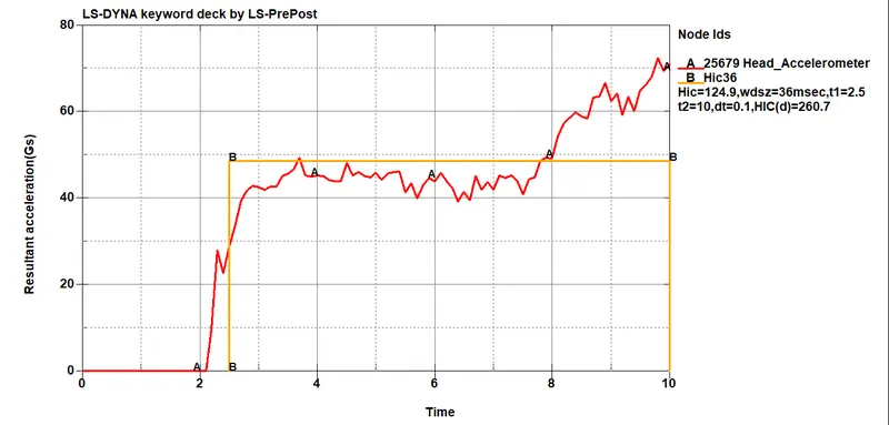
HIC-
HIC CALCULATIONS
The HIC value is calculated using the following formula:

We shall be considering case 3 for these calculations.
From the plot,
The average value of acceleration for the time interval of t1=2.5 ms and t2=10 ms is given by the following formula: 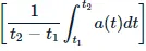 which is equal to 48.5.
Therefore, HIC =
HIC(d) =
The HIC and HIC(d) values obtained from the plot in case 3 are 124.9 and 260.7 respectively. The manually calculated values are 123.114 and 259.28 - they are not too far off from the plotted values and are hence acceptable.
OBSERVATIONS
The obvious difference between the cases (especially case 3 and the others) is the rigid wall and its effects. In cases 1 and 2, due to the non-deformable nature of the rigid wall, the head has to absorb most of the impact. Whereas, that is not the case in case 3. The hood absorbs most of the impact and hence the stresses are generated in the hood, compared to stresses being generated in the head in cases 1 & 2.
With the rigid wall not softening the impact, the energy plots also experience sudden changes. For example, in cases 1 & 2, we can see that there is a massive drop in kinetic energy after impact, whereas it's more gradual in case 3.
The hood being deformable also plays a big factor in the HIC value for case 3. As we can see, the HIC value is 124.9, which is much lesser than the NCAP threshold of 650. Whereas, the HIC values are much higher and past the threshold in cases 1 & 2 (1.386e+08 & 2.746e+04), meaning they are completely unsafe. The lower the HIC value, the higher the impact absorption by the body colliding with the head.
RESULT
The given head models were simulated in three cases, with the first case involving a simple head coming in contact with a rigid wall, the second case involving the provided child's head coming in contact with a rigid wall at an angle mimicking real-world conditions and the third case contained simulation of the head coming in contact with the provided meshed hood at an angle.
The HIC value in case 3 was lower than the NCAP threshold of 650, meaning the impact was mostly absorbed by the hood. This is why hoods are designed to deform and not cause damage to pedestrians when accidents happen. If the hood is not deformable, it could be fatal to the pedestrian and can cause deadly head injuries (as seen by the extremely high HIC values in cases 1 & 2). The deformation is key as it absorbs the impact.
LEARNING OUTCOME-
1. LEARNED HOW TO DO A EXPLICIT ANALYSIS FOR A HEAD IMPACT ON A CAR HOOD.
2. LEARNED ABOUT MASS SCALING AND HOW WE CAN REDUCE SIMULATION TIME.
3. THIS PROJECT THOUGHT ME HOW WE CAN INCLUDE DIFFERENT FILES TO RUN A SIMULATION.
4. LEARNED THE THEORY BEHIND DOING A EXPLICIT ANALYSIS AND ABOUT THE HEAD IMPACT TEST.