Week 9-Creation of 1D Connectors Challenge
Aim-
To generate 2D mesh on the given components and create connectors to attach them.
Objective –
Generating mesh as per the given quality criteria by using the 2d auto mesh option and creating connectors to attach the below components as per the given type of connectors.
Quality criteria –
- Aspect Ratio – 5
- Skewness – 45
- Warping – 15
- Taper - 0.5
- Length – 2 units
- Length – 8units
- Min angle Quad – 45
- Max angle Quad - 135
- Min angle Tria - 30
- Max angle Tria - 110
- Tria % 10
List of components and type of connectors to be used-
- Right_Rail_2 & Front_truss_1: - Seam-Quad(angled+capped+L)
- Left_Rail_2 & Front_truss_1: -Quad elements
- Front_truss_2, Front_truss_1 & Right_Rail_1: - Spot weld with 2 Layers and 5 mm Diameter
- Front_truss_2, Front_truss_1 & Left_Rail_1: - Hexa (Adhesive)
- Rear_truss_2 & Right_Rail_2: - Bolt Connector
- Rear_truss_2 & Left_Rail_2: - Bolt Connector
- Right_Rail_1 & Right_Rail_2: - Spot-weld with Rigid Elements
- Left_Rail_1 & Left_Rail_2: - Spot-weld with Spring Element
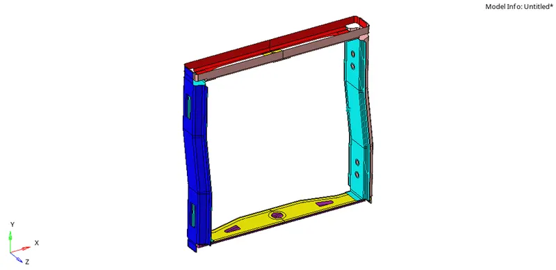
Image 1 – model given for challenege
Procedure-
1. Import the required geometry using the import option under the title bar and menu bar and import using geometry choose the file type (IEGS, STEP).
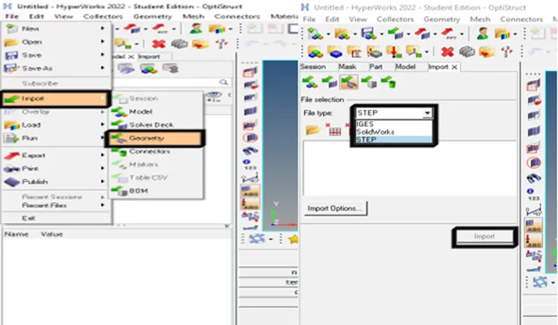
Image 2- importing the model
2. After importing the file now, we have to check for solids. For checking solids go to the by topo view and if solids are present delete the solids by using the delete option and select the component and delete the solid.
(Tools-> delete-> solids-> select solids-> delete)
3. After deleting the solids now, we have to generate a 2D mesh to the whole component by using the auto mesh tool. But before meshing edit the quality criteria file and set it as per the given quality criteria. After changing the quality criteria file mesh, the components by using the auto mesh tool and change the element size to 5mm after that select the surfaces and mesh.
(2D -> auto mesh-> target element size-> surfaces -> mesh)
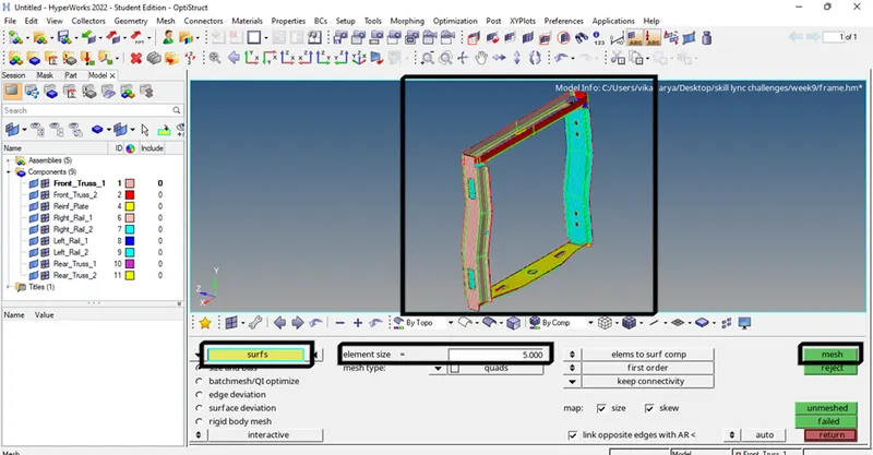
Image 3- meshing the component
4. After meshing the components now we have to create the connectors to them one by one as per the given list.
Creating the connectors-
a. Right_Rail_2 & Front_truss_1: - Seam-Quad(angled+capped+L)
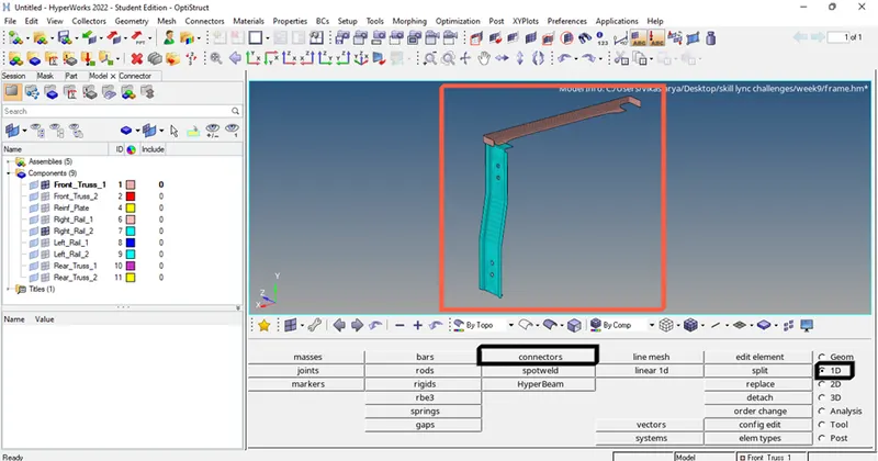
Image 4. Right_Rail_2 & Front_truss_1
(1D-> connectors -> seam-> type-> nodes-> components -> tolerance-> create)
1. The first connector we have to create is Seam-Quad(angled+capped+L). To create this connector, we have to use the connector tool which is present in the 1D option. Click on the connector tool and select the seam option, inside the seam option now we have to choose the type of seam weld we want which is Seam-Quad(angled+capped+L).
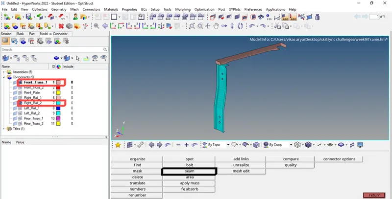
Image 5- selecting the type of connector
2. After changing the type, select the nodes from the required location which have to be attached by the connector. Next, now we have to select the components need to be attach and provide the tolerance as 10mm. and click on create.
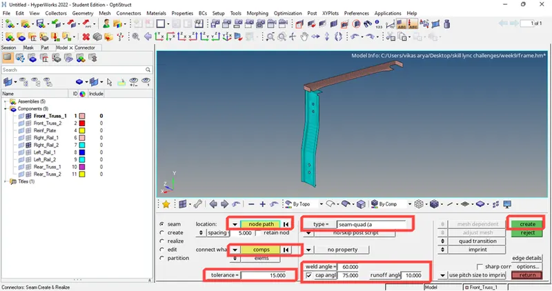
Image 6- creating a connector on required components
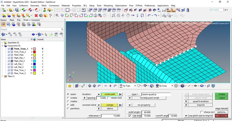 I
I
mage 7- selecting the nodes
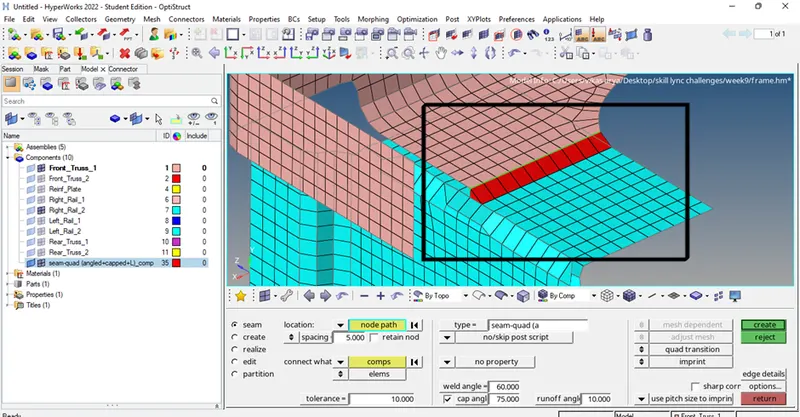
Image 8- Seam-Quad(angled+capped+L) type connector has been created.
3. After creating the seam connector now, we have to check whether the connector is realized or not. To check go to the view option in the title bar and select the browse option under that choose hyper mesh and click on connectors.
(Title bar->view->browse->hypermesh->connectors)
4. After opening the connectors check the type of connector so we have used the seam as a connector, check the seam and check the state if it shows the green color that means the connector is successfully created between the given components.
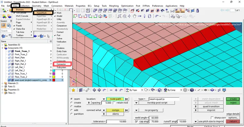
Image 9- opening the connector tab on the tab area to check the status of the connector.
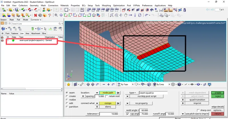
Image 10- verifying the state of the connector.
b. Left_Rail_2 & Front_truss_1: - Quad elements-
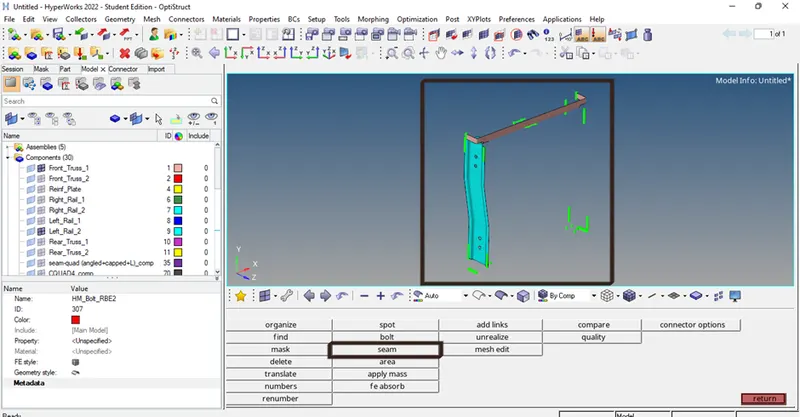
Image 11- Left_Rail_2 & Front_truss_1.
1. The first connector we have to create is Quad elements. To create this connector, we have to use the connector tool which is present in the 1D option. Click on the connector tool and select the seam option, inside the seam option now we have to choose the type of seam weld we want which is Quad elements.
(1D-> connectors -> seam-> type-> nodes-> components -> tolerance-> create)
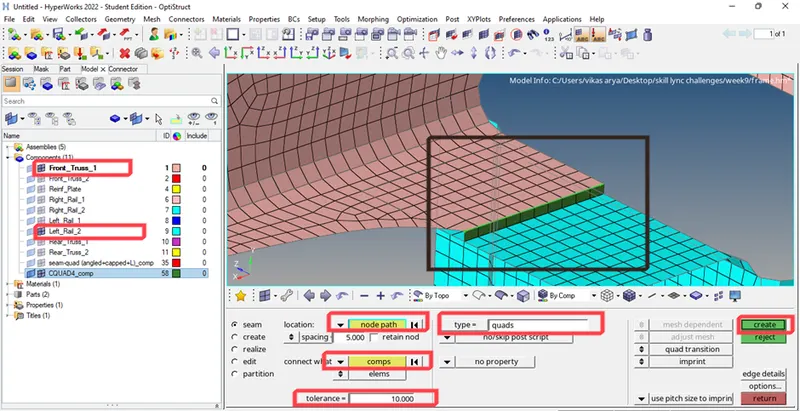
Image 12- creating the connector
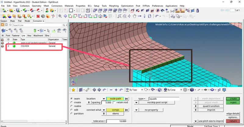
Image 13- verifying the status
c. Front_truss_2, Front_truss_1 & Right_Rail_1: - Spot weld with 2 Layers and 5 mm Diameter-
1. The first connector we have to create is a Spot weld with 2 Layers and 5 mm Diameter. To create this connector, we have to use the connector tool which is present in the 1D option. Click on the connector tool and select the spot option, inside the spot option now we have to choose the type of spot weld.
(1D-> connectors -> spot-> type-> nodes-> components -> tolerance-> diameter-> create)
2. After selecting the type put the given parameters for the connectors such as the diameter of 5mm and the number of layers as 2.
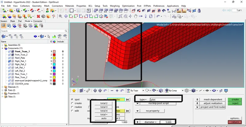
Image 14- creating the connector
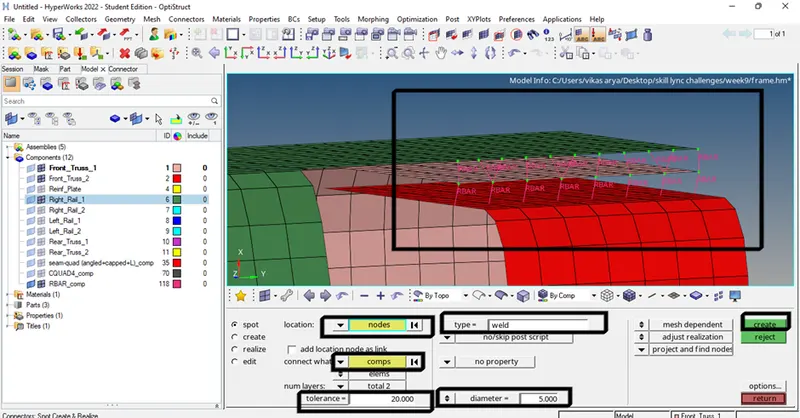
Image 15 – spot weld has been created
d. Front_truss_2, Front_truss_1 & Left_Rail_1: - Hexa (Adhesive)-
1. The first connector we have to create is Hexa (Adhesive). To create this connector, we have to use the connector tool which is present in the 1D option. Click on the connector tool and select the seam option, inside the seam option now we have to choose the type of seam weld we want which is Hexa (Adhesive).
(1D-> connectors -> seam-> type-> nodes-> components -> tolerance->coats-> strips -> width-> create).
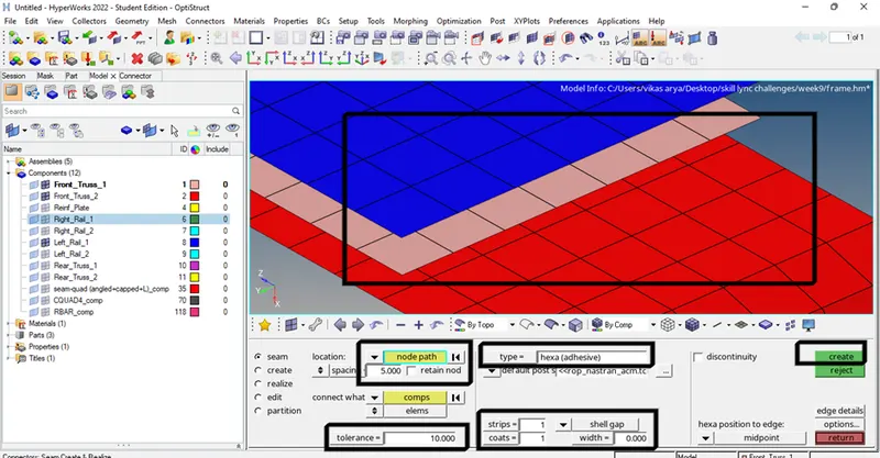
Image 16- creating the connector.
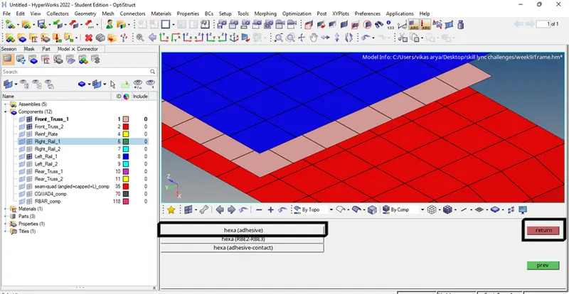
Image 17- selecting the type of connector
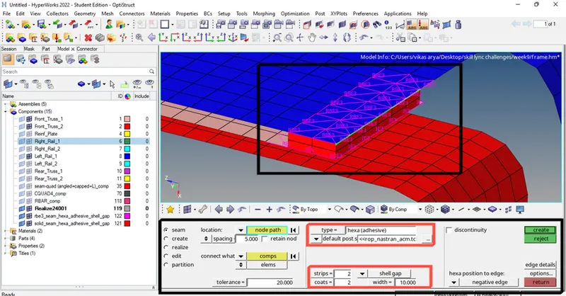
Image 18- hexa adhesive connector has been created by using negative edge and with 2 coats 2 strips.
2. After changing the type and parameters now we will see the use of the edge position option as in the above image the adhesive coats are inside because the edge position is used as negative, now we will see with different positions but we have used the nodes on the outer edge so we have to use the negative position. The edge positions depend on the location of the nodes we select.
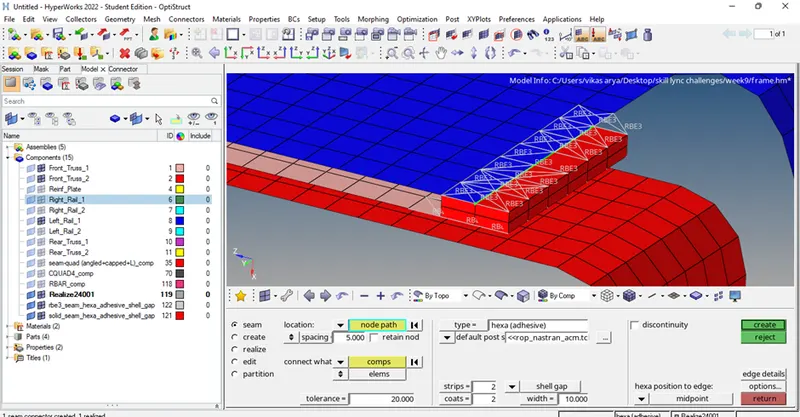
Image 19- adhesive coating with edge position as the midpoint
Image 20- adhesive coating with edge position as positive
3. We have to create the connector to attach three components by using hexa adhesive so now we will select the three components together and create the connector.
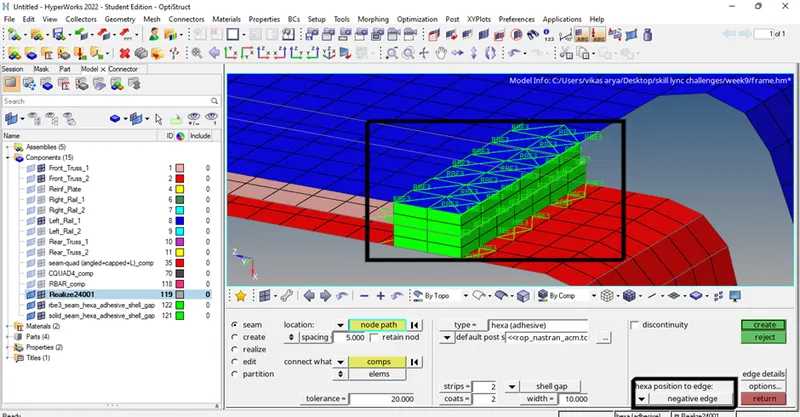
Image 21- hexa adhesive connectors have been created between the components.
e. Rear_truss_2 & Right_Rail_2: - Bolt Connector-
f. Rear_truss_2 & Left_Rail_2: - Bolt Connector-
1. Now we have to create bolt-type connectors to attach the two truss and two rails components.to create the bolt connector go to the connector tool and select the bolt option, after selecting the bolt option set the parameters as per requirements as we have not created the holes at the required location so we have to change the option to Create hole if none.
(1D-> connectors -> bolt-> type of bolt-> nodes -> Components-> number of layers -> tolerance-> create hole-> create)
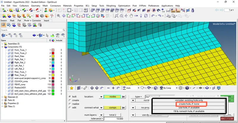
Image 22- changing parameters as per requirement
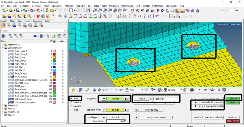
Image 23- bolt connector has been created.
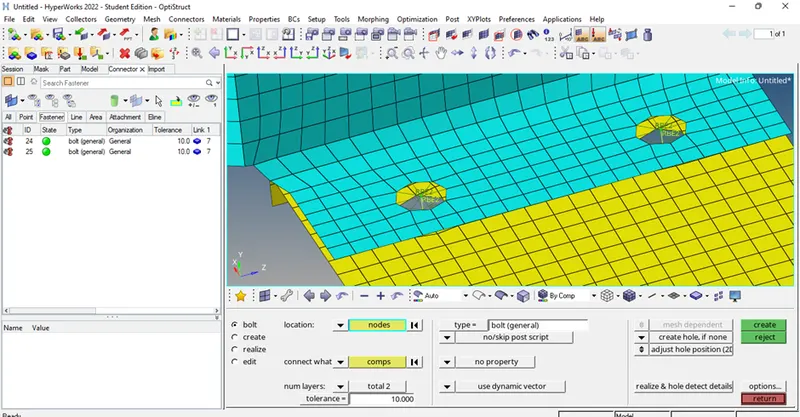
Image 24- verifying the status of the bolt connectors
g. Right_Rail_1 & Right_Rail_2: - Spot-weld with Rigid Elements-
1. The first connector we have to create is Spot-weld with Rigid Elements. To create this connector, we have to use the connector tool which is present in the 1D option. Click on the connector tool and select the spot option, inside the spot option now we have to choose the type of spot weld.
(1D-> connectors -> spot-> type-> rigid-> nodes-> components -> tolerance-> diameter-> create)
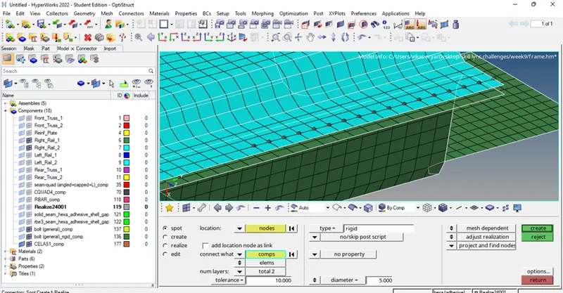
Image 25- creating the spot weld with rigid element connector
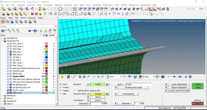
Image 26- connector has been created successfully.
h. Left_Rail_1 & Left_Rail_2: - Spot-weld with Spring Element-
1. The first connector we have to create is Spot-weld with spring elements. To create this connector, we have to use the connector tool which is present in the 1D option. Click on the connector tool and select the spot option, inside the spot option now we have to choose the type of spot weld.
(1D-> connectors -> spot-> type-> spring-> nodes-> components -> tolerance-> diameter-> create)
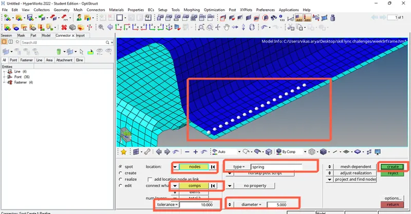
Image 27- creating the connector
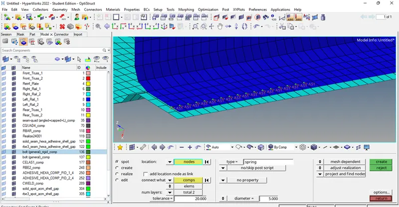
Image 28- connector has been created successfully
I. Connectors used for other components-
1. Hexa (adhesive-contact)-
(1D-> connectors-> seam-> type-> hexa (adhesive-contact)-> nodes -> components-> tolerance-> create)
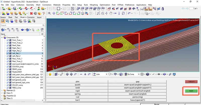
Image 29- creating hexa (adesive-contact)
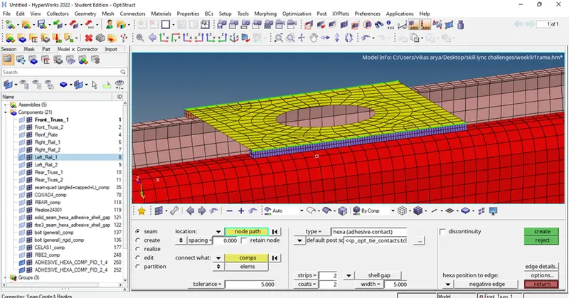
Image 30- connectors has been created successfully
2. Spot weld (Rod)-
(1D-> connectors-> spot-> type->Rod-> nodes -> components-> tolerance-> diameter -> create)
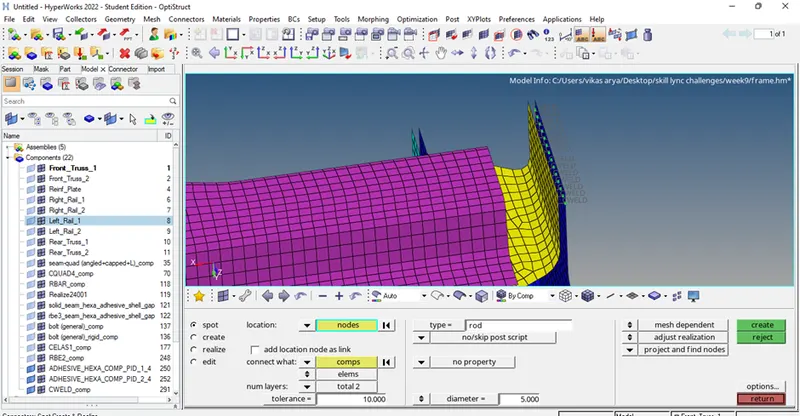
Image 31- connectors has been created successfully
3. Spot (Amc general)-
(1D-> connectors-> spot-> type->Amc general-> nodes -> components-> tolerance-> diameter -> create)
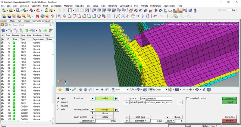
Image 32- connector has been created successfully
Conclusion –
Given components are meshed properly as per given quality criteria and connectors has been created successfully on the given components as per the required parameters.
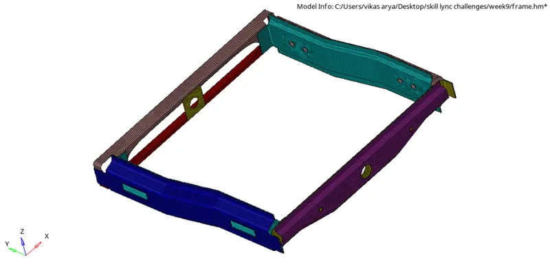
Image 33- components are meshed successfully with 2D elements
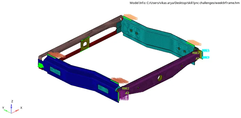
Image 34- Connectors has been created successfully on the required components
Output of the challenge-
After completing this challenge, I learned about the type of connectors and there uses and how we can create the connectors on the required location to attach the components.