Week 4-1D Element Creation Challenge
Aim- 1. To create a 1D element on the given parallel bracket model as per the required cross-sections.
Objective-
1. Creating 1d element on a parallel bracket by generating a mid surface from the solid surfaces of the parallel bracket using the mid surface tool and creating different types of 1d elements after doing the proper mesh. Property should be assigned in the provided 1d elements by using the hyper beam tool as per the given cross-sections.
a. Rod element: - Translational DOF should be Constrained with the RBE2 link.
Cross-Section: BOX- Dimension a= 12 m
dimension b=10 mm
Thickness t= 0.75 mm
b. Beam element: - All DOF should be constrained with RBE3 link
Cross-Section: I Section- Dimension a= 8 mm
Dimension b= 10 mm
Dimension c= 8.5 mm
Thickness t1= 0.75 mm
Thickness t2= .6 mm
Thickness t3= .6 mm
c. Bar element: - Constrain only x and y DOFs With the RBE3 link
Cross-section: X section- Dimension DIM1= 5 mm
Thickness DIM2= 1.2 mm
Dimension DIM3= 10 mm
Thickness DIM4= 1.2mm
d. At d & e Apply the mass of magnitude 10 with the RBE2 link.
f. At f Join the two components with Spring elements.
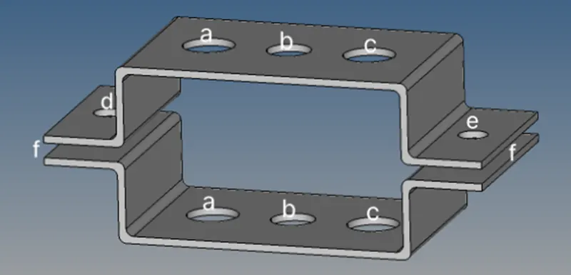
Image-1
Procedure-
1. Steps for Importing the required file-
a. Open the IGIS file by using the import geometry option in the title bar and changing the file type option as per the file format.

Image-2
2. Steps for creating the mid surface-
a. To create the mid surface in the imported model use the mid surface tool from the pre-processing tool panel and select the auto mesh option by offset+plane+sweep after this click on the reference surfaces where we have to create the mid surface and then click create now you can hide the solid surface to make mid surface more visible.
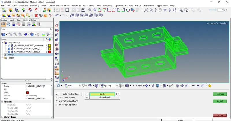
Image-3
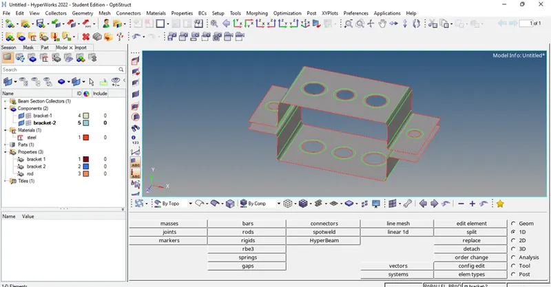
Image-4
3. Steps to mesh the mid surfaces-
a. Before meshing the mid surface use the washer split tool in the quick edit option in the tool panel after that select the holes one by one to give the washer split and click to generate.
b. After creating the washer split on the holes go to the 2d option in the main menu panel and select the auto mesh option in the tool in the tool panel, after selecting the mesh tool select the surface which has to be mesh and select the size of the elements as 5units then create the mesh.
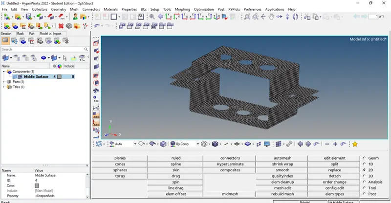
Image- 5
4. Steps to create 1d elements-
1. To create a rod element- Go to the main menu panel and select the 1D element option and go to the rigid option to create an RBE2 element by selecting the required nodes and keep all DOF constrained for this element and then click on create do same for the other bracket. After creating the RBE3 element go for the options and select the element type to CROD to create a rod element by which we can connect the two brackets by a rod. after creating the rod element now, we have to assign the property to the rod element by creating box cross-section by using hyper beam option as per the given cross-section and assigning the property to the rod by updating the element using rod tool option.
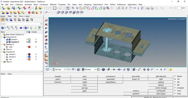
Image-6
2. To create a beam element- Go to the main menu panel and select the 1D element option and go to the RBE3 to create a Rbe3 element by selecting the required nodes and keep the translational DOF constrained for this element and then click on create do same for the other bracket. After creating the RBE3 element go for the bars options and select the element type to CBEAM to create a BEAM element by which we can connect the two brackets by a beam. After creating the beam element now, we have to assign the property to the element by creating (I) cross-section by using the hyper beam option as per the given cross-section and assigning the property to the beam element by updating the element using the bars tool option.
3. To create a bar element- Go to the main menu panel and select the 1D element option and go to the RBE3 to create a Rbe3 element by selecting the required nodes and keep the X and Y DOF constrained for this element and then click on create do same for the other bracket. After creating the RBE3 element go for the bars options and select the element type to CBAR to create a BAR element by which we can connect the two brackets by a bar. After creating the bar element now, we have to assign the property to the element by creating an (X) cross-section by using the hyper beam option as per the given dimensions and assigning the property to the beam element by updating the element using the bars tool option.
4. To create a mass element- Go to the main menu panel and select the 1D element option and select the masses tool in the panel and assign the 10unit mass by selecting the required nodes from both brackets on both sides of the parallel bracket as shown in the image below.
5. To create a spring element- Go to the main menu panel and select the 1D element option and select the spring tool in the panel and assign the element type CELAS1 by selecting the required nodes from both brackets on both sides of the parallel bracket as shown in the image below.
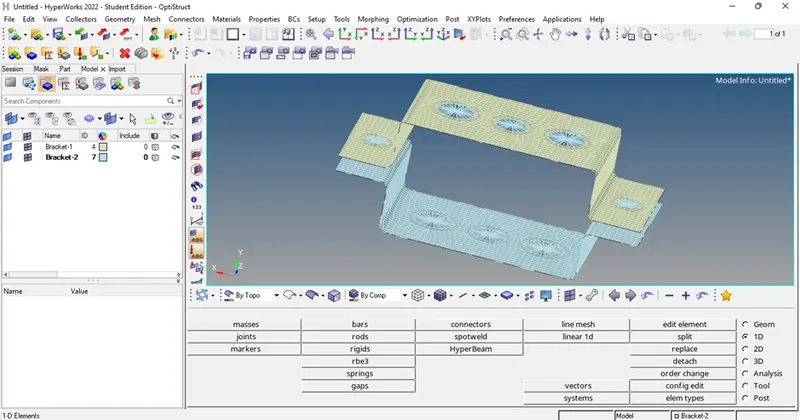
Image-7
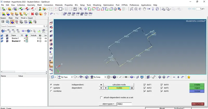
Image- 8
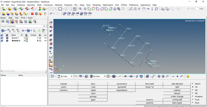
Image-9
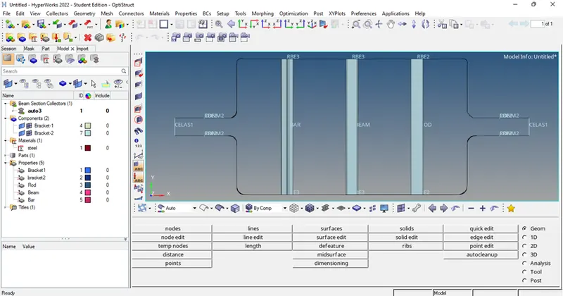
Image-10
Conclusion-
Given parallel bracket has been properly meshed using 5 unit element size and 1D elements are created as per given boundary conditions and with proper dimensions as shown in the image-10 below.
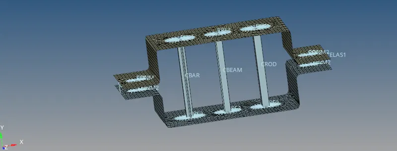
Image-10
The outcome of the challenge-
After completing the given challenges, I got familiar with the pre-processing tools of the hypermesh and the use of the correct tool for achieving accurate results. I learned how to mesh a cad model with accuracy and how to create mid surfaces in a solid surface and how to create 1d elements as per the required dimensions.