Week 12:Project 2-Meshing of Rear Wheel Holder challenge
AIM-
Pre-processing of Sheetmetal component known as “SPARE WHEEL CARRIER PLATE” of the car using HYPER MESH.
OBJECTIVE-
- Clean up the geometry until no topological error is found.
- Extract Mid-Surface for the geometry.
- Meshing according to given quality criteria.
- Improving mesh flow without any quality issues.
- To assign thickness to the component.
QUALITY CRITERIA TO BE FOLLOWED:
- Aspect Ratio - 5
- Skewness - 45
- Warping -15
- Taper - 0.5
- Length - 2 units
- Length - 8units
- Min angle Quad - 45
- Max angle Quad - 135
- Min angle Tria - 20
- Max angle Tria - 120
- Tria % - 10
THEORY-
Thomas Morris Davies created the Stepney spare wheel in 1904; at the time, early motor vehicles were manufactured without light wheels, making a puncture something that all drivers dreaded.
The ingenious concept of Mr Davies was to create a spokeless wheel rim with an inflated tyre. A spare tyre, often known as a Stepney, is an extra tyre kept in a car in case one blows out, goes flat, or experiences any other emergency.
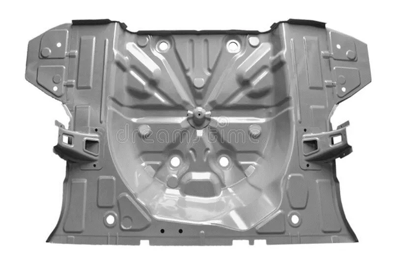
Image-1 Spare wheel sheet metal panel.
A structural shear panel is created by combining top, bottom, and a core with vacuum-infused resin to build a floor panel that will be supported by a vehicle frame.
The top and bottom layers of the core are each made of a honeycomb panel that defines a collection of hexagonal tubular cells with walls that extend in the thickness direction and are individually filled with foam.
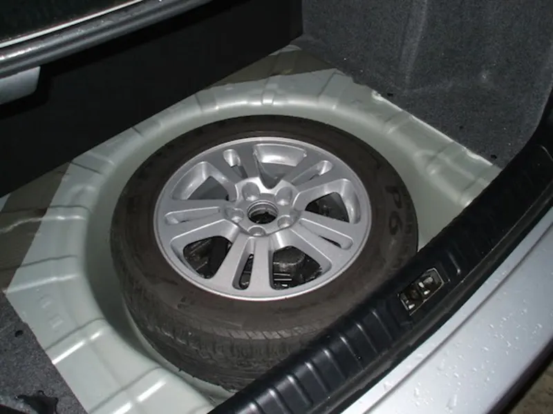
Imgae-2 Spare wheel in the sheet metal support panel.
PROCEDURE-
1. Open the given format file in the hyper mesh by using the import geometry option.
2. Change the file format to required one and select the required file from the file location.
3. After selecting the file click on the import option and the required model will appear in the graphics area.
(Files-> import-> geometry-> iges format -> select required file-> import)
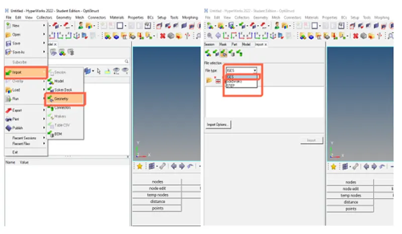
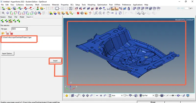
Image -3 Importing the geometry.
4. Check for the damaged surfaces and try to fix them manually.
5. To fix the required damaged surfaces use the surface tool option and choose the surface through lines option select the required lines to make the proper surface.
(Geom-> surfaces-> ruled->select the lines -> create)
Or
(2D-> spline->lines->surface only ->select the lines->create)
6. For fixing the surface damage quickly use the quick edit tool and use the filler surface option to fill the open or damaged surfaces.
(Geom-> quick edit-> filler surf)
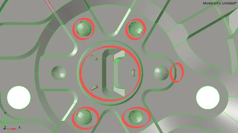
Image- 4 Geometrical errors.
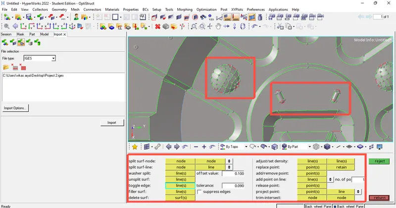
Image- 5 Cleaning the geometrical errors by using quick edit tools.
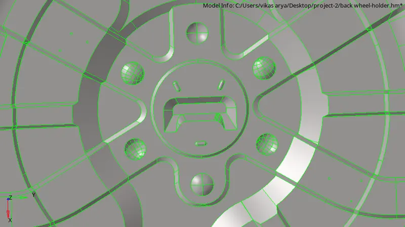
Image- 6 Component after geometrical cleaning.
7. After cleaning the model now, we have to create the midsurface. To create the midsurface in the imported model use the midsurface tool from the pre-processing tool panel and selecting the auto mesh option by skin offset after this click on the reference surfaces where we have to create midsurface and the click create now you can hide the solid surface to make midsurface more visible.
(Geom->midsurface-> extraction options->skin offset->auto midsurface ->select the surf-> create)
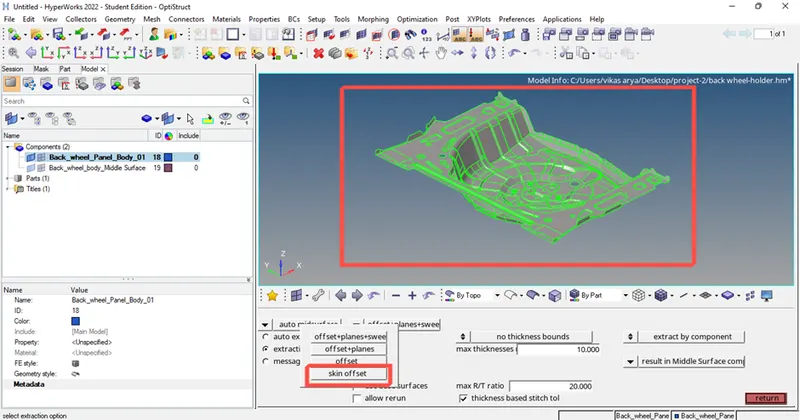
Image- 7 extrating the midsurface using skin auto-midsurface tool.
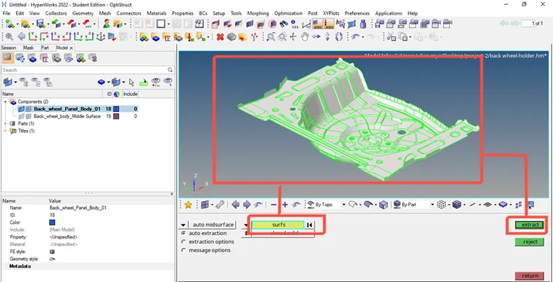
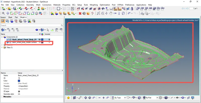
Image- 8 Generated midsurface.
8. After generating the mid surface for every part now we have to mesh each component one by one.
PROCEDURE MESH GENERATION-
1. For creating mesh click on the 2d option in the main menu tool panel and choose the auto mesh option and set the required criteria and with elements of 5 units.
2. Before meshing set the conditions as per the given quality criteria. To set the quality criteria choose the option element clean-up from the tool panel and click on the edit criteria and set all the given quality criteria and click apply. After setting the parameters choose the edit parameter option and set all the required values such as element size etc.
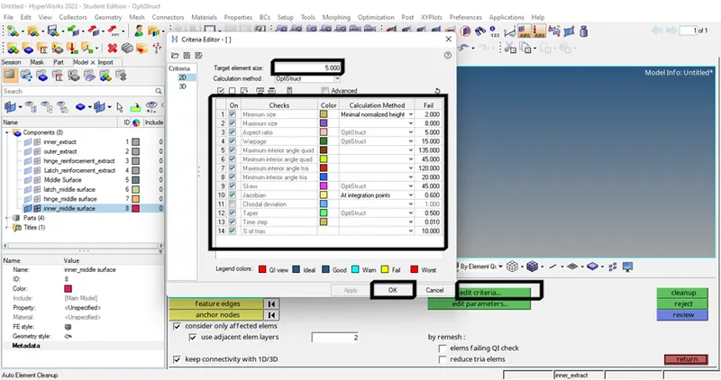
Image- 9 Setting the quality criteria parameters.
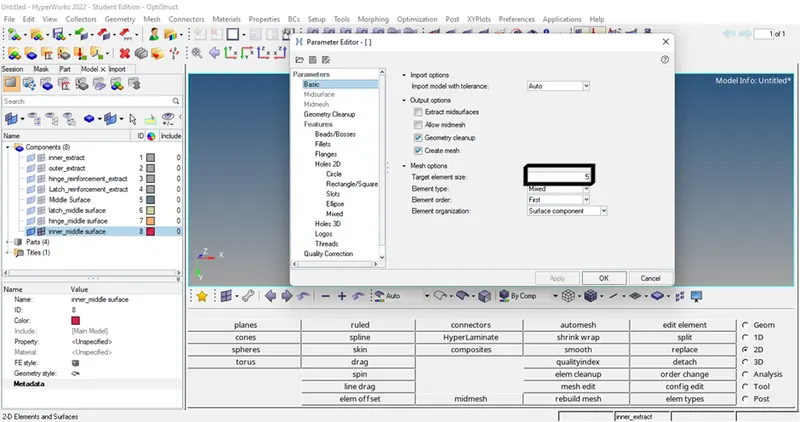
Image- 10 Setting the required parameter file.
3. After setting the quality criteria now we have to create good mesh quality and mesh flow. To create good mesh flow split the geometry in simple shapes like rectangle, square etc. if complicated shapes are generated then there will be no proper mesh flow and the number of nodes of a particular shape should be same on each side if it is not same mesh will be improper.
4. Use to split the model by taking care of seeing the feature lines and construction lines but in proper shapes and toggle the unwanted lines by using quick edit tool.
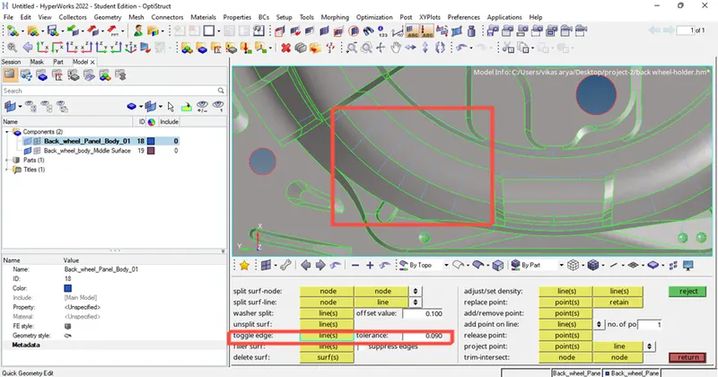
Image- 11 Unwanted constructions lines are toggled mentioned as blue lines.
5. Before meshing we have to look at some meshing terminology such as-
- No tria elements should be opposite to each other.
- No tria should be near to the critical regions such as hole fillets etc.
- There should be less tria concentration.
- Maintain as much as quad elements for proper mesh flow and analysis.
6. After splitting as per required way now we can mesh the given model by using elements size 5.
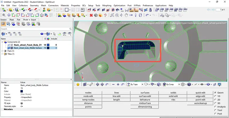
Image- 12 Meshing region by region by splitting the surface properly.
7. As we know for proper analysis, we have to use quads elements in meshing so for proper mesh flow we have to maintain as much as quad elements and prevent tria elements in the part so, after meshing now we have check for the quad elements and clean all tria elements by using mesh optimizing tools.
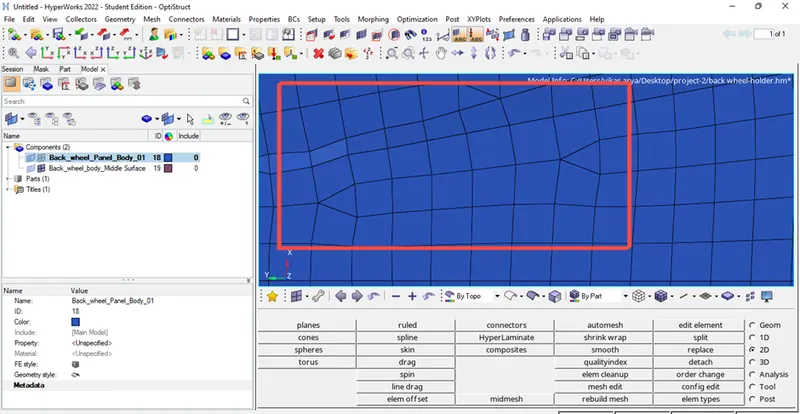
Image 13- Tria elements present in the mesh.
PROCEDURE FOR ELIMINATING THE TRIA ELEMENTS –
1. Go to the 2d option in tool panel and choose the option edit element and then click on the split option choose the start point and drag make the splitting line as per required shape and click on split now you can see two triangles join the two triangles by using quality index option. In this option do to the clean-up tools and combine the two trias using the same option in the panel.
(2D->edit element->split option-> split)
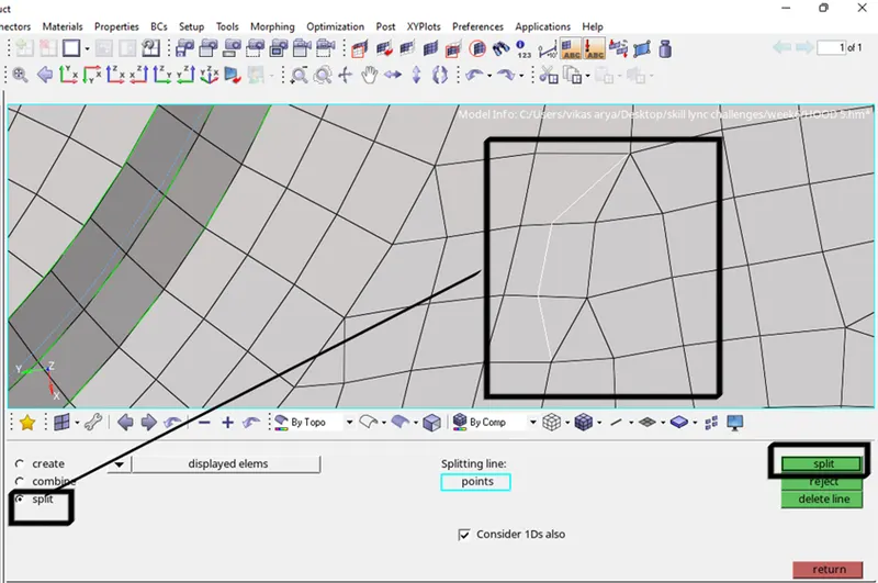
Image- 14 Splitting the elements using edit element tool.
(2D->quality index->clean-up tools-> combine two trias -> ok)
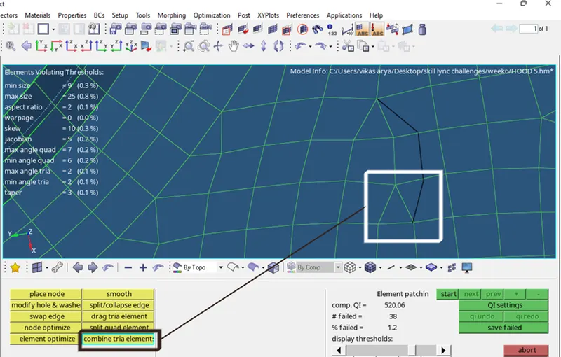
Image- 15 Combining two tria elements.
PROCEDURE FOR FIXING THE QUALITY OF THE ELEMENTS-
1. To make element quality accurate we have to use a tool called as element optimize tool. So, to optimize the tool we have go into 2d option in the main menu tool panel and choose the quality index option and go under clean-up tools option inside this option we have to click on the element optimize option and select the elements which has to be optimize.
(2D->quality index->clean-up tools-> element optimize)
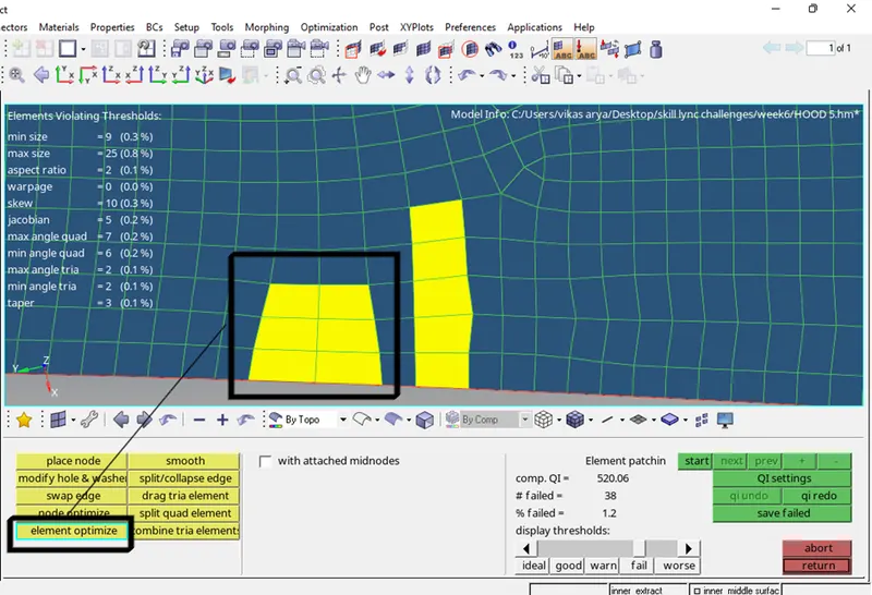
Image- 16 Elements with yellow colour needs to be optimize.
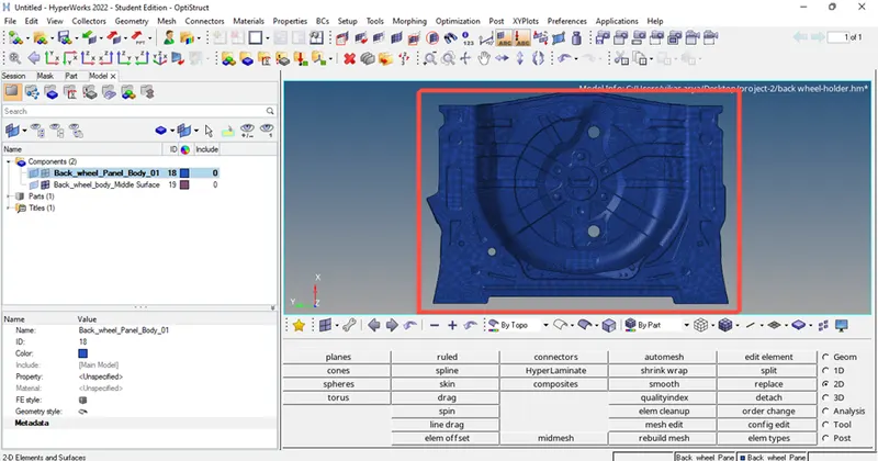
Image- 17 Fully meshed component.
PROCEDURE FOR CHECKING THE MESH QUALITY AND ELEMENT QUALITY-
1. After the meshing process we have to check the mesh quality for the particular part, so to check the quality we have to go to the 2d option in the main menu panel and select the quality index option and if it is clean-up tools option change it to QI setting option and check the quality percentage and no of elements are failing in the left corner of the screen. To fix the element again we have to use cleanup tool in same option.
(2D->quality index->QI setting)
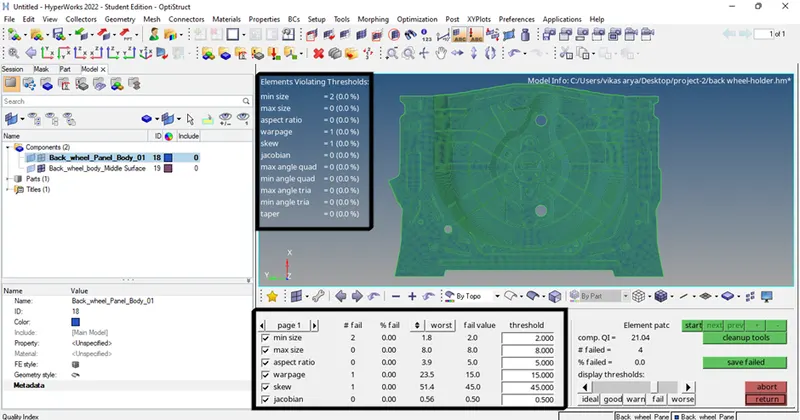
Image- 18 Mesh quality check.
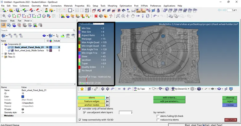
Image- 19 Element quality check.
PROCEDURE FOR ASSIGNING THICKNESS TO THE MESHED COMPONENT:
1. For assigning thickness to the component first we need to create component of different thickness.
(Go component panel -> right click > create -> component)
2. Now we need to create property and put the thickness value of individual as shown in below figure.
(Right click on panel -> create property -> put thickness value)
Here thickness we have to provide is 0.75mm.
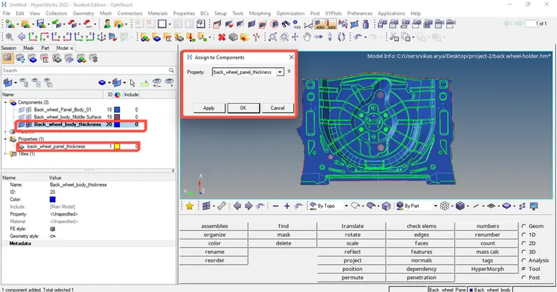
Image- 20 Assigning thickness property to the meshed component.
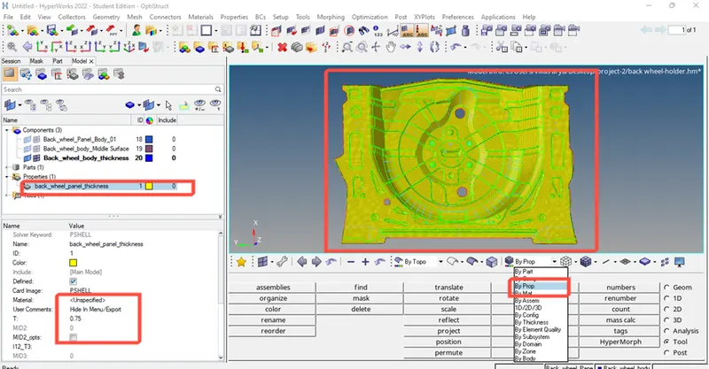
Image- 21 Thickness property is successfully assigned to the component.
CONCLUSION-
- This component's midsurface is successfully extracted.
- There are no geometrical errors during any elemental clean-up.
- All provided quality requirements have been met during meshing.
- Clean-up tools and numerous more techniques have eliminated all elemental failure.
- The feature lines were completed.
- Less elemental failure has been used to obtain a good mesh flow.
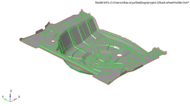
Midsurface of the component achieved successfully.
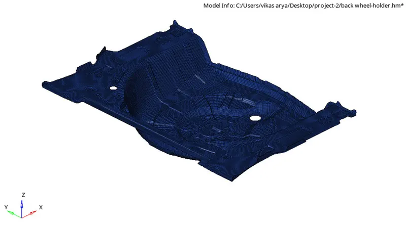
Meshing was achieved on the generated midsurface successfully.
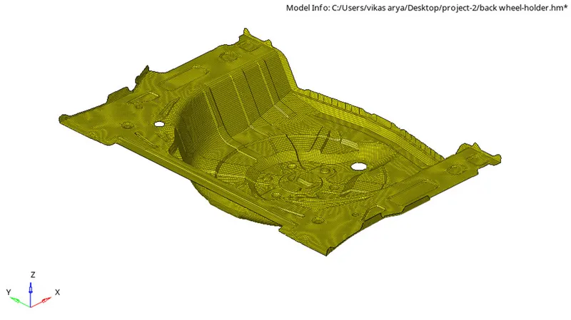
Thickness property assigned to the meshed component successfully.
OUTCOME OF THE PROJECT-
- I learned how to manually extract midsurfaces for complex geometry through this project.
- How to deal with the geometry in complicated models.
- How to mesh properly while maintaining a nice mesh flow and how to prevent elemental failure with a low tria percentage.
- How to ultimately assign separate components a thickness.