Week 6-Meshing of Hood Challenge
Aim- Creating mesh on a given CAR HOOD CAD model by following the given quality criteria.
Objective- Generating mesh on the cad model of a car hood as per the quality criteria shown below. To achieve this, the cad model should be cleaned from geometrical errors by using clean-up tools and a proper mid-surface of the cad models should be performed. The car hood model consists of three different parts, 1) the inner part of the hood, 2) the outer part of the hood, 3) hinges reinforcements, 4) latch reinforcement. The middle surface has to be created before creating mesh on the individual.
Quality criteria-
- Aspect Ratio – 5
- Skewness – 45
- Warping – 15
- Taper - 0.5
- Length – 2 units
- Length – 8units
- Min angle Quad – 45
- Max angle Quad - 135
- Min angle Tria - 20
- Max angle Tria - 120
- Tria % 10
Cad model-

Image-1 inner part
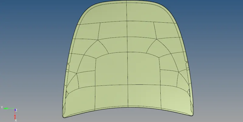
Image-2 outer part
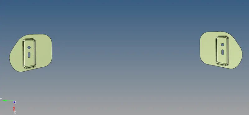
Image-3 hinges reinforcements
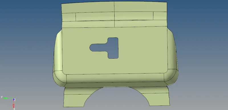
Image-4 latch reinforcement
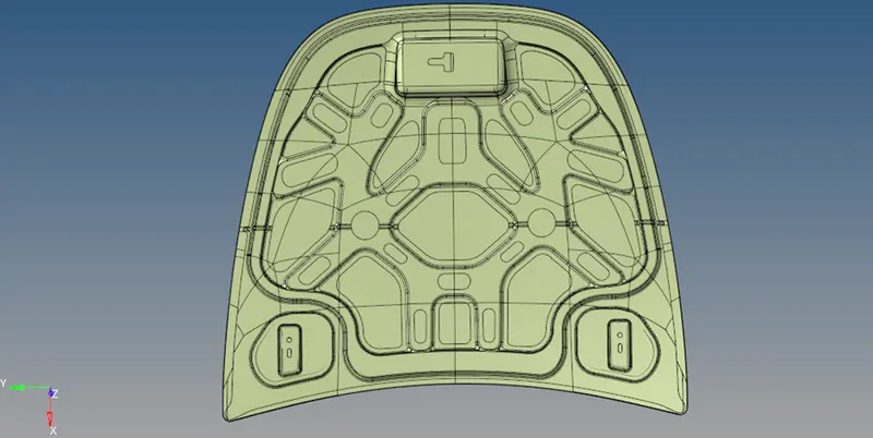
Image-5 full cad model of a car hood
Procedure-
1. Open the step. File in the hyper mesh by using the import geometry option.
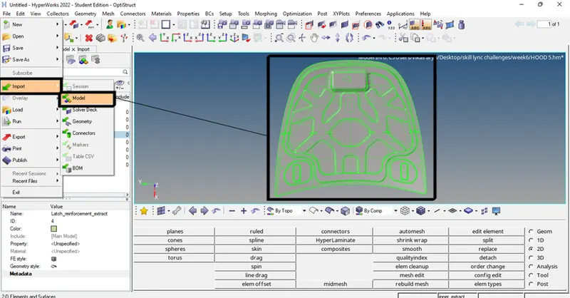
Image -6 importing the geometry
2. Check for the damaged surfaces and try to fix them manually.
3. To fix the required damaged surfaces use the surface tool option and choose the surface through lines option select the required lines to make the proper surface.
(Geom-> surfaces-> rueld->select the lines -> create)
Or
(2D-> spline->lines->surface only ->select the lines->create)
4. For fixing the surface damage quickly use the quick edit tool and use the filler surface option to fill the open or damaged surfaces.
(Geom-> quick edit-> filler surf)
5. After cleaning the model now, we have to create the midsurface. To create the midsurface in the imported model use the mid surface tool from the pre-processing tool panel and selecting the auto mesh option by skin offset after this click on the reference surfaces where we have to create midsurface and then click create now you can hide the solid surface to make the mid surface more visible.
(Geom->midsurface-> extraction options->skin offset->auto midsurface ->select the surf-> create)
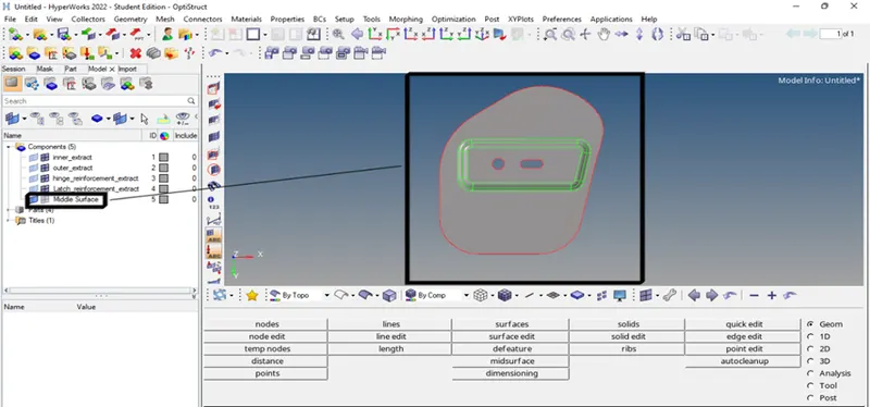
Image- 7 generating the midsurface on hinge reinforcement
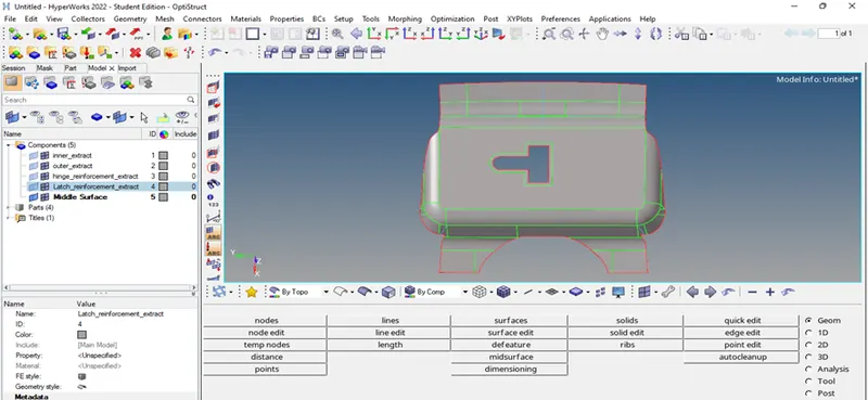
Image- 8 mid surface has been generated for latch reinforcement
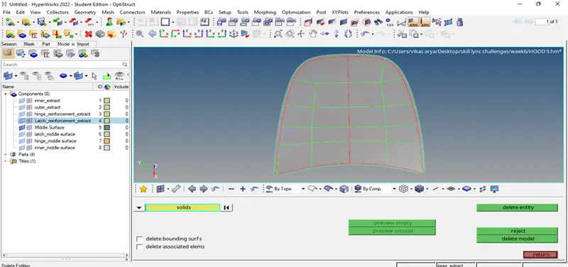
Image- 7 mid surface of the outer part of the hood
6. The different components should be created separately for each part mentioning the midsurface for different parts and component name should be given as per parts.
7. After generating the mid surface for every part now we have to mesh each component one by one.
Procedure Mesh generation-
1. For creating mesh click on the 2d option in the main menu tool panel and choose the auto mesh option and set the required criteria and with elements of 5 units.
2.Before meshing set the conditions as per the given quality criteria. To set the quality criteria choose the option element clean-up from the tool panel and click on the edit criteria and set all the given quality criteria and click apply. After setting the parameters choose the edit parameter option and set all the required values such as element size etc.
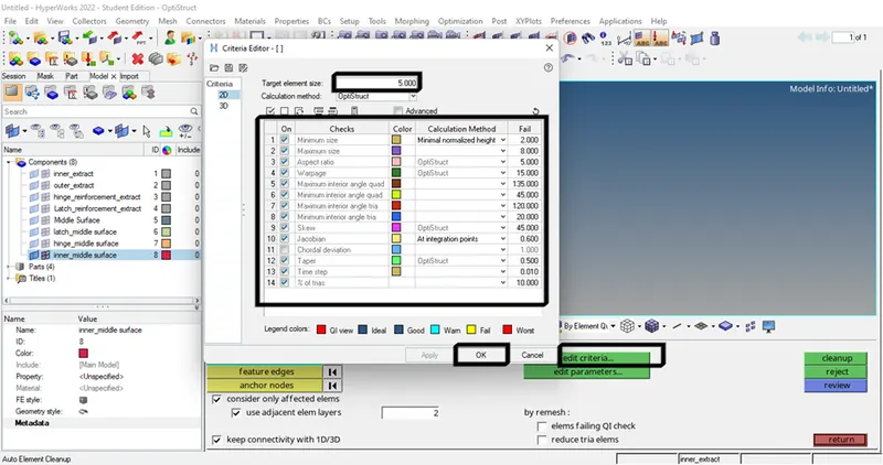
Image 8- setting the quality criteria parameters
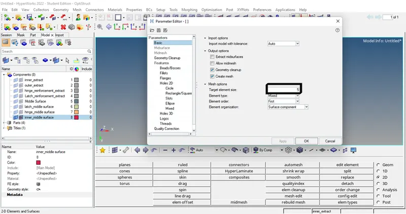
Image 9- other required parameters
3. After setting the quality criteria now we have to create good mesh quality and mesh flow. To create good mesh flow split the geometry into simple shapes like rectangles, squares,s, etc. if complicated shapes are generated then there will be no proper mesh flow and the number of nodes of a particular shape should be the same on each side if it is not same mesh will be improper.
4. Use to split the model by taking care of seeing the feature lines and construction lines but in proper shapes and toggle the unwanted lines by using the quick edit tool.
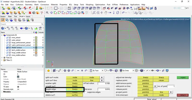
Image 10- unwanted construction lines are toggled and mentioned as blue lines.
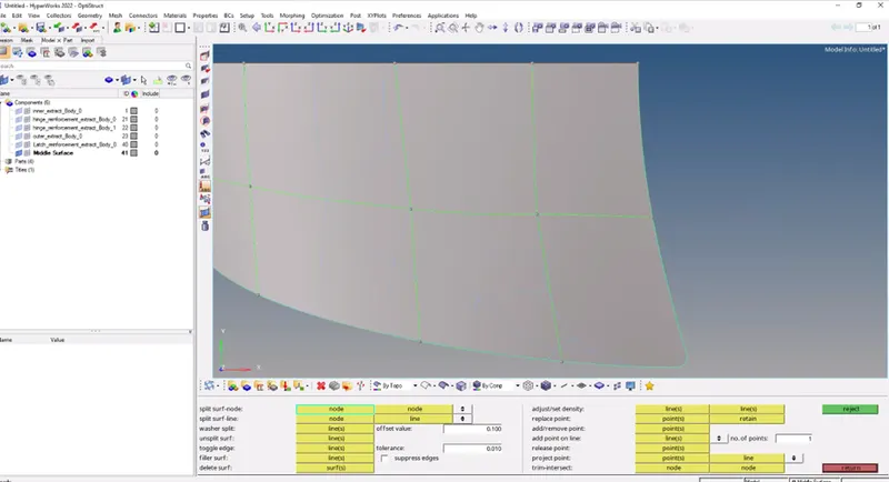
Image 11- proper splitting
5. Before meshing we have to look at some meshing terminology such as-
a. No tria elements should be opposite to each other.
b. No tria should be near the critical regions such as hole fillets etc.
c. There should be less tria concentration
d. Maintain as many as quad elements for proper mesh flow and analysis.
6. After splitting as per the required way now we can mesh the given model by using elements size 5.
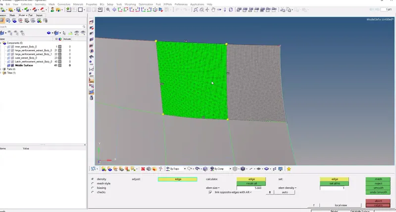
Image 12- proper meshing using a splitting process
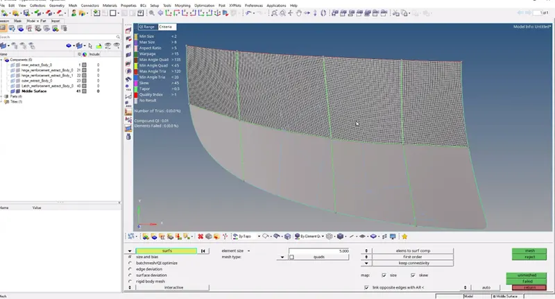
Image 13- proper mesh with no trias
7. As we know for proper analysis, we have to use quads elements in meshing so for proper mesh flow we have to maintain as many as quad elements and prevent tria elements in the part, after meshing now we have to check for the quad elements and clean all tria elements by using mesh optimizing tools.
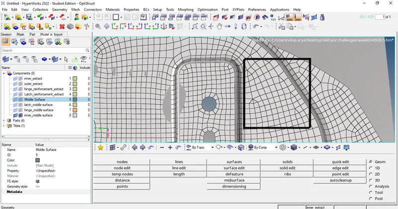
Image 11- continuous tria elements present in the mesh
Procedure for eliminating the trias –
1. Go to the 2d option in the tool panel and choose the option edit element and then click on the split option choose the start point and drag make the splitting line as per the required shape and click on split now you can see two triangles join the two triangles by using a quality index option. In this option do the clean-up tools and combine the two trias using the same option in the panel.
(2D->edit element->split option-> split)
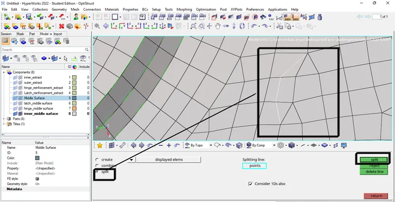
Image 12- splitting the elements using edit element tool
(2D->quality index->clean-up tools-> combine two trias -> ok)
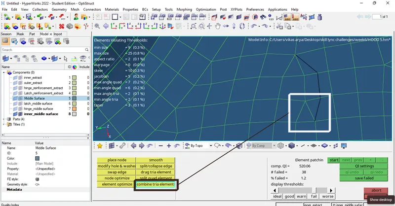
Image 13- combining two trias
Procedure for fixing the quality of the elements-
1. To make element quality accurate we have to use a tool called an element to optimize the tool. So, to optimize the tool we have gone into the 2d option in the main menu tool panel and choose the quality index option and go under the clean-up tools option inside this option we have to click on the element optimize option and select the elements which have to be optimized.
(2D->quality index->clean-up tools-> element optimize)
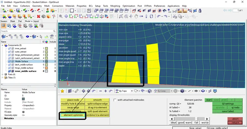
Image 14- elements with yellow colour needs to be optimize
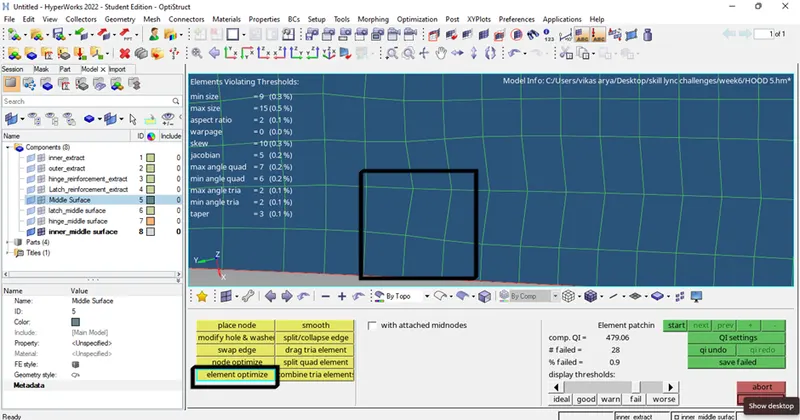
Image 15- elements after optimization
Procedure for checking the mesh quality and element quality-
1. After the meshing process we have to check the mesh quality for the particular part, so to check the quality we have to go to the 2d option in the main menu panel and select the quality index option and if it is clean-up tools option change it to QI setting option and check the quality percentage and no of elements are failing in the left corner of the screen. To fix the element again we have to use the cleanup tool in the same option.
(2D->quality index->QI setting)
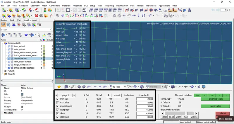
Image 16- mesh quality check
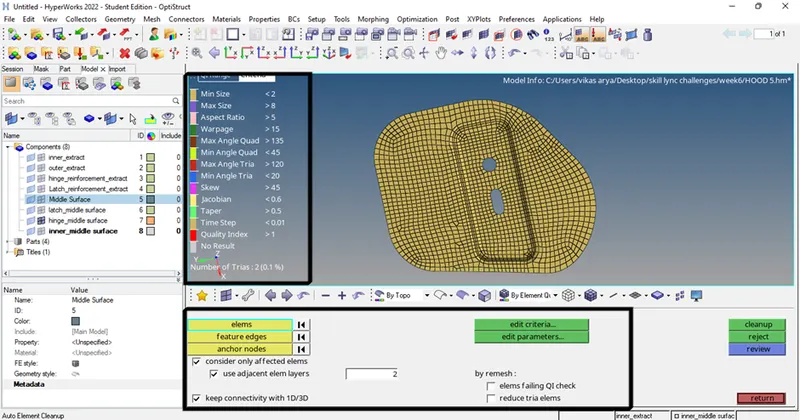
Images 17- checking element quality
The same procedure should be followed for each part given. Images shown below are parts with proper mesh as per given quality criteria.
1. Outer extraction model.
Tips- If the given model is symmetric split it into half and mesh the half region and reflect the other half.
(Tool->delete->surfaces->delete)
(Tool-> reflect->surface/elements-> duplicates->current component ->select the surface/elements->axis of reflecting-> base node-> reflect)
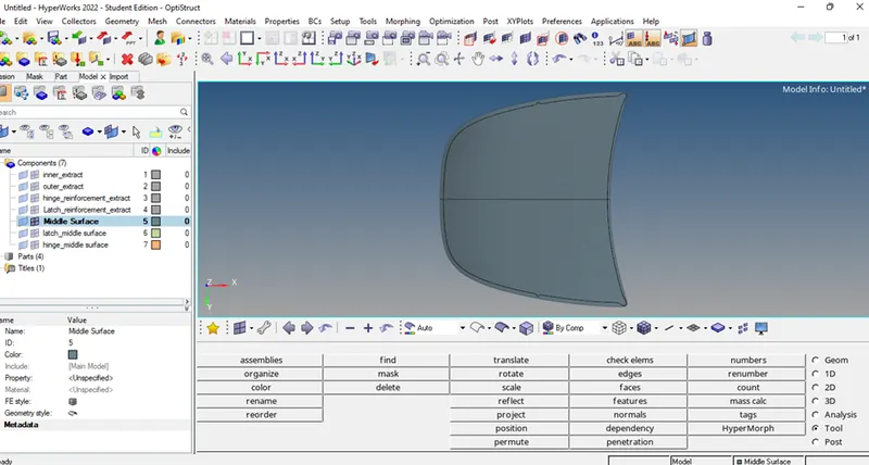
Image 18- fully meshed outer part
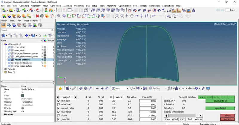
Image 19- quality check
2. Latch reinforcement part-
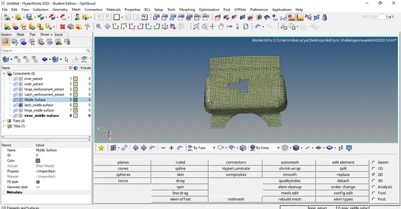
Image 20- latch model with proper mesh
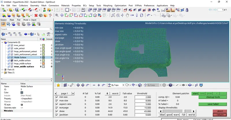
Image 21- quality check
3. Hinge reinforcements-
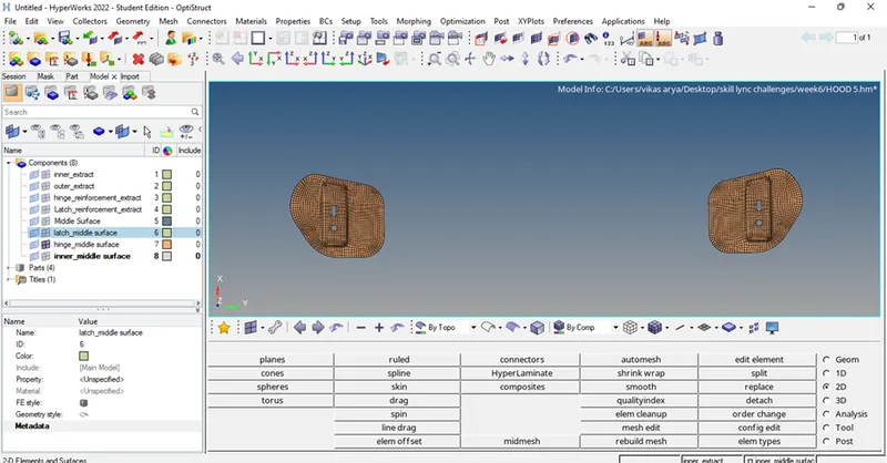
Image 22- hinges with proper mesh
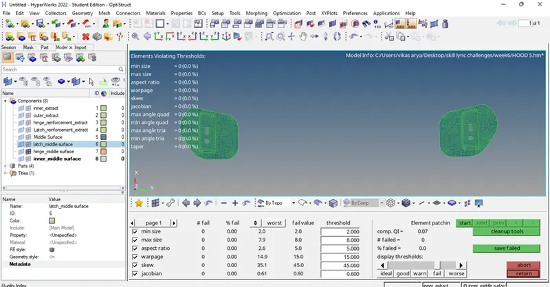
Image 23- mesh quality check
4. Inner panel-
1. To mesh the inner part, we have to delete the half surfaces from the middle because the geometry is symmetric on both sides so, to make the process easy we can delete the half surfaces and after generating the mesh we can reflect the mesh on the other half surface.
To reflect- (Tools-> reflect -> surfaces-> select the surface ->duplicate ->current component -> select the vector or direction of reflection-> base node ->reflect)
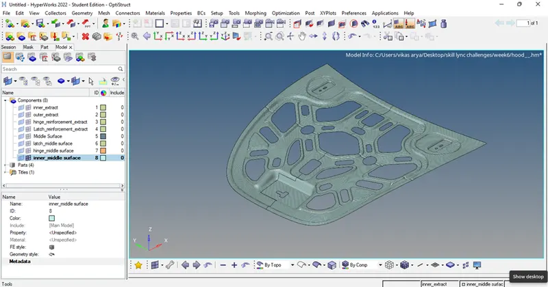
Image 24- 2d mesh has been achieved
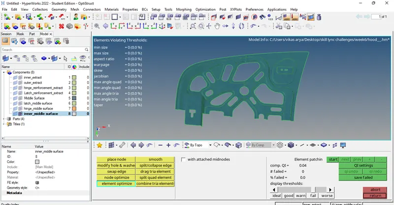
Image 25- mesh quality check.
Conclusion-
2D mesh has been achieved using a 2D mesh model on the different components of the CAR HOOD CAD model as per the given quality criteria.
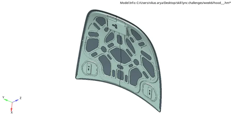
Image 26- All components with 2D mesh