Creating connection for Rear door of a vehicle in ANSA.
Aim:
To Create connection for Rear door FE model.
Objective:
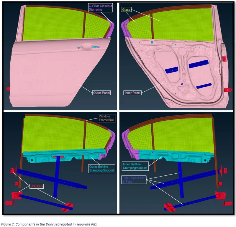
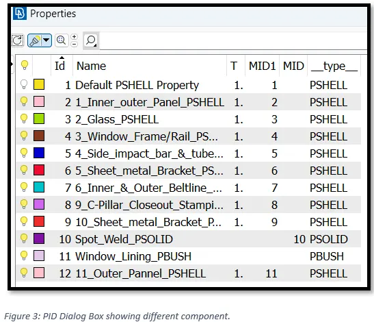
- Create and apply different PIDs for different components.
- Perform suitable connections.
Introduction:
Connectors
The connector is simply a database of information defining a specific request for connection at a specific location. OR, Connectors are a geometric representation of connections between entities. The advantage of connectors is the ability to create multiple connections at a single time.
They can be used to create numerous types of connection elements such as:
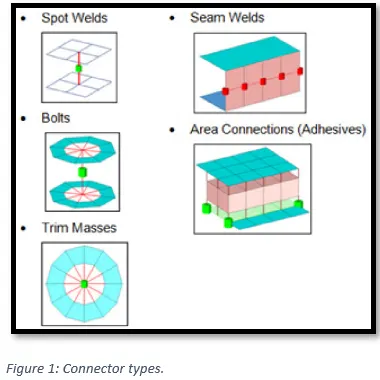
A connector definition describes the connector between multiple entities at a specific location. Entities that are to be connected are referred to as link entities. The connector location can be defined as a node or node list, a geometric point, a line or line list, a surface, or even as elements or tags.
Generally, to establish connectors, 1D elements are used. 1D elements can be used to connect nodes together, attach dissimilar meshes, distribute loads and in general provide a quick and easy way to attach things together.
There are numerous types of 1D elements ranging from infinitely rigid simple connections to complex cross sectioned elements that can be stressed.
Following 1D elements can be found in ANSA under NASTRAN deck: CBAR, CBEAM, RBE2, RBE3, ROD etc.
Procedure:
1) Importing the FE-model.
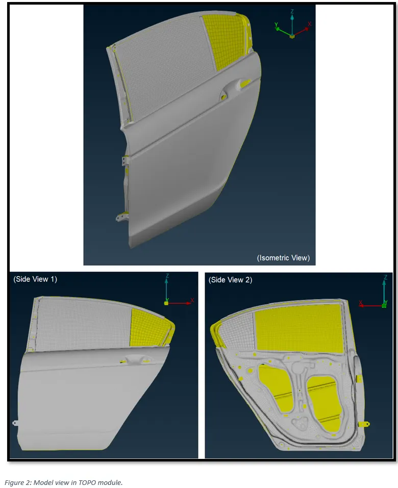
2) Segregating sub-componenets in different PID.
3) Establishing Connections.
3.1) RBE2 Many nodes connection
In the Model there are bracket plated with holes to join the door with the vehicle body through a bolt connection. Since we only have a door, thus the bolt connection between the Bracket joining the door with the vehicle body can not be established.
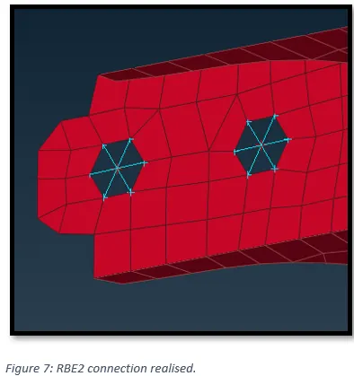
But we will fill the bracket hole with a “RBE2 Many Node” element. This may represent bolt connection on one side. And during the vehicle integration process hole in the vehicle body can be used to realise a bolt connection (either using RBE2 element again or connection manager).
Since we will be connecting more than 2 nodes hence, we will select Many Nodes RBE2 option.
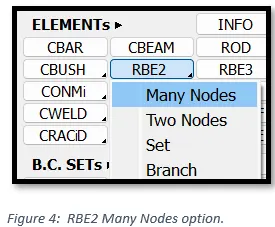
To make connections, switch to NASTRAN deck module. Go to, Elements -> RBE2 -> Many Nodes.
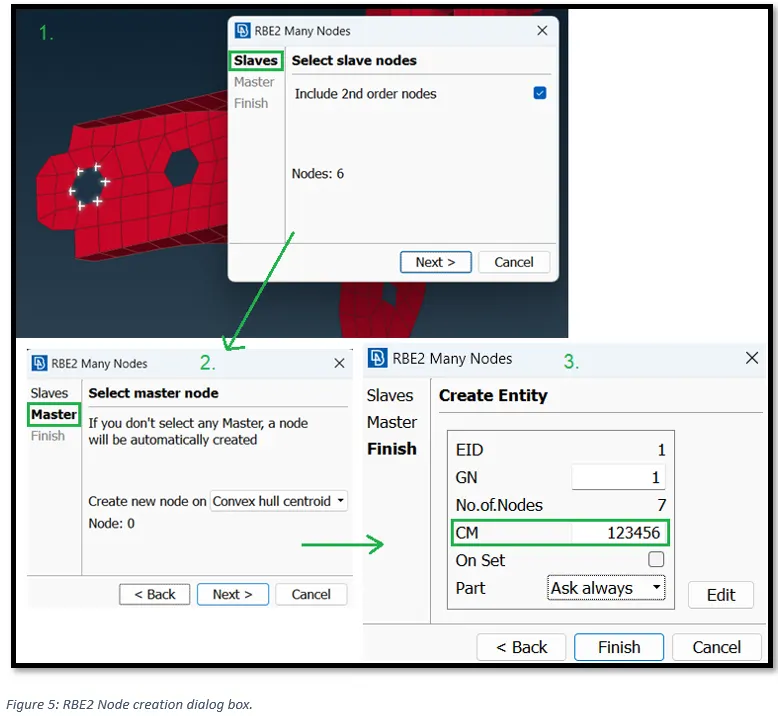
Then we will select slave nodes (Dependent node) and the master node (Independent node). CM (Constraint Motion) represents DOF that we want to constraint. Put CM = 123456, to constraint translational and rotational motion in x, y and z axis.
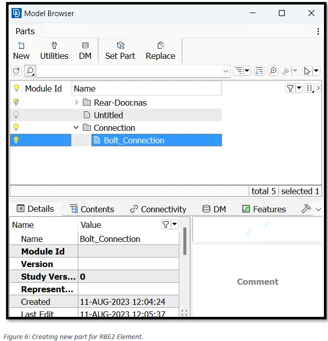
Next, depending on the option selected, ANSA may prompt us to create a new part for the RBE2 element. New part can be created by selecting, New -> Part.
3.2) Bolt Connection with washer.
To represent a washer with bolt in FE model, we need to create zone cut in the FE. To do that switch to the Mesh module, go to, Shell Mesh - > Zone Cut.
After forming the zone cut, we need to create RBE2 elements. Switch to NASTRAN deck module, go to, Elements -> RBE2 -> select the zone elements -> middle click to accept.
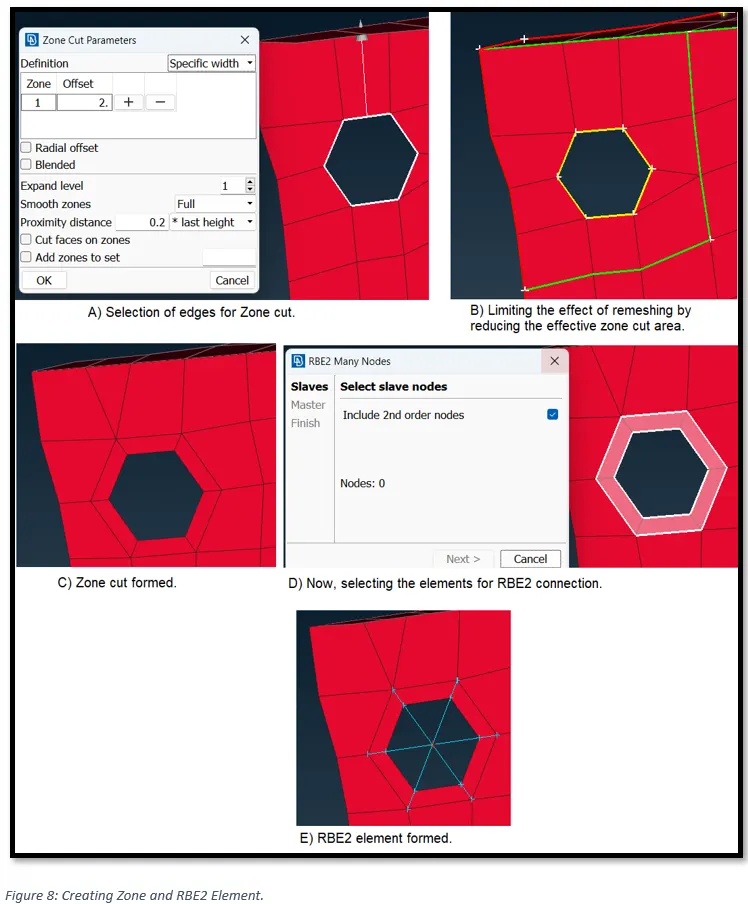
3.3) Bolt and Nut Connection to join two surfaces.
To make a Bolt and Nut connection. First, we need to create “Many nodes RBE2” elements in the two holes and then we need to join the master node of the two RBE2 elements with a “Two nodes RBE2 element”.
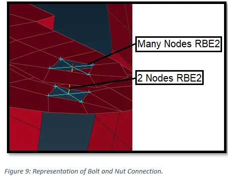
3.4) Bolt and Nut connection to join three surfaces.
Another way of creating a Bolt and Nut connection is by using “Connection Manager”.
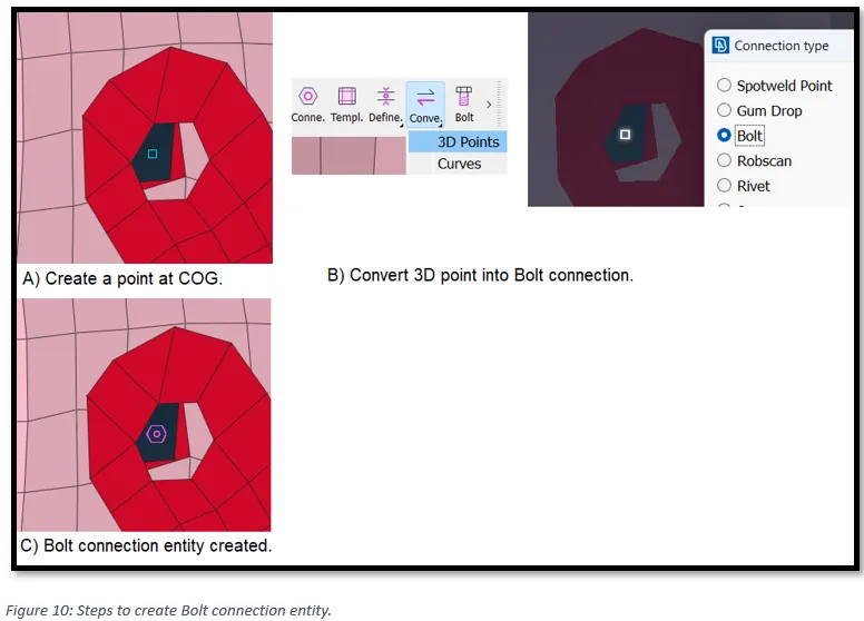
Firstly, Create a point at the centre. Go to, Topo module -> Points -> on COG -> select the hole edges -> middle click.
Secondly, in the Assembly section, convert the 3D point into a bolt connection type. This will create a bolt connection entity.
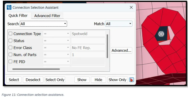
In the Assemble section, select the connection manager this will open “connection selection assistance” dialogue box. Select the bolt connection entity.
Now ANSA will prompt us to “Connection manager” window. Select the options as shown in the Figure 12.
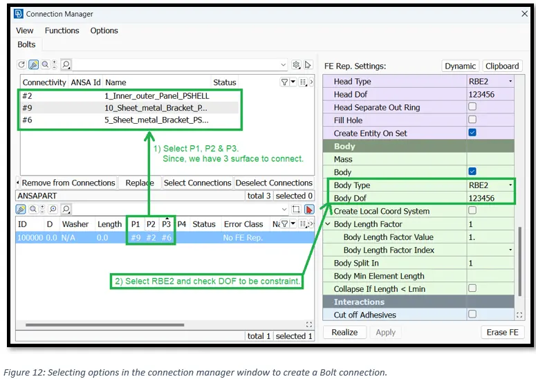
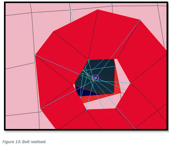
Finally, click on “Realize” to create the bolt connection.
3.5) Creating hinge connection.
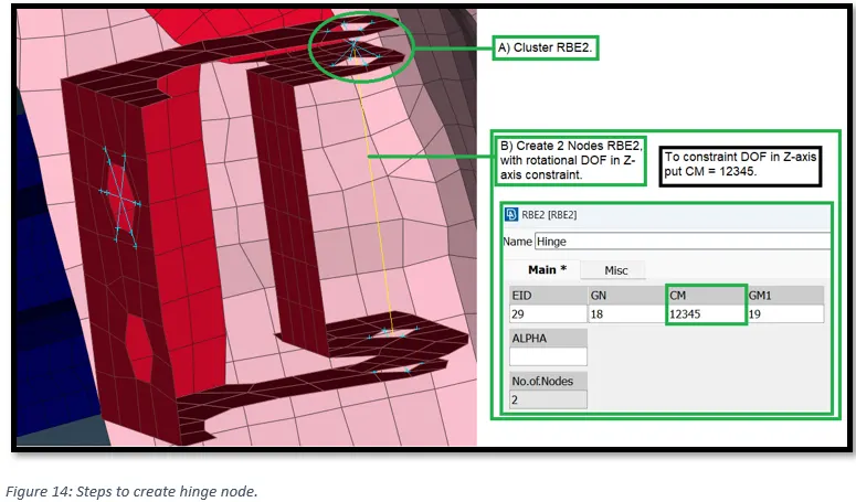
To establish a hinge connection, first, we need to form “cluster/ Many node RBE2” connection at the upper and lower end of the two brackets. Then from the two Master node of the Cluster RBE2 elements create a “2 Node RBE2” element. Refer Figure 14.
As a hinge connection allow rotation motion along an axis. And since, the hole axis is parallel to the global z-axis, hence we are not going to constraint the rotation motion along the z-axis. To do that put “CM = 12345”
3.6) Creating RBE3 spot weld connection.
Firstly, Create a point at the centre. Go to, Topo module -> Points -> on COG -> select the element edges -> middle click.
Secondly, in the Assembly section, convert the 3D point into a “Spot weld point” connection type. This will create a spotweld connection entity.
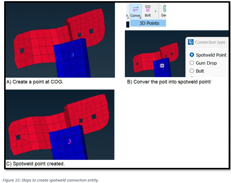
In the Assemble section, select the connection manager this will open “connection selection assistance” dialogue box. Select the spotweld connection entity.
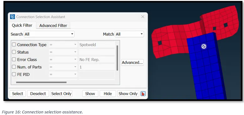
Now ANSA will prompt us to “Connection manager” window. Select the options as shown in the Figure 17.
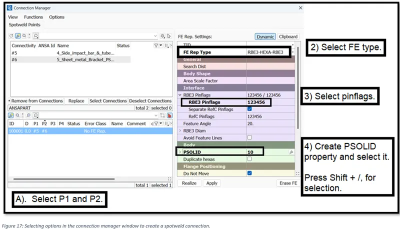
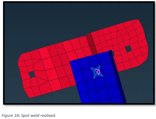
Fnally, click on “Realize” to create the bolt connection.
3.7) Capturing door handle with mass element.
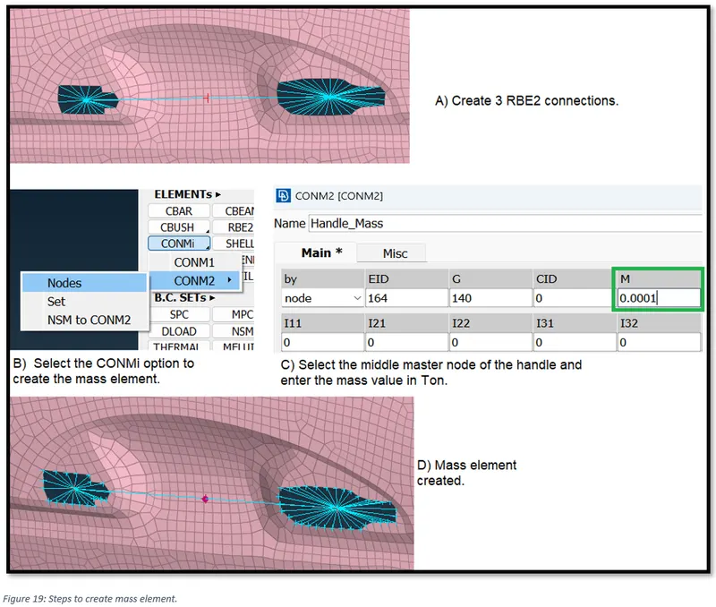
Assuming mass of the door handle = 100gm or 0.0001 Ton. Select the options as shown in the Figure 19, to create mass element at the centre of the handle.
3.8) Creating connections for weather strips/ window rail (CBUSH).
To create damping elements in 3 direction we use CBUSH element.
Create curve around the window perimeter. Go to, Mesh module -> Perimeters -> Feat2Curve.
This curve should be converted to seam line connection. To do that, go to -> Connection -> curve -> select the curve -> choose seam line.
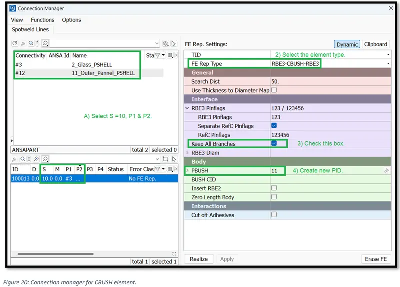
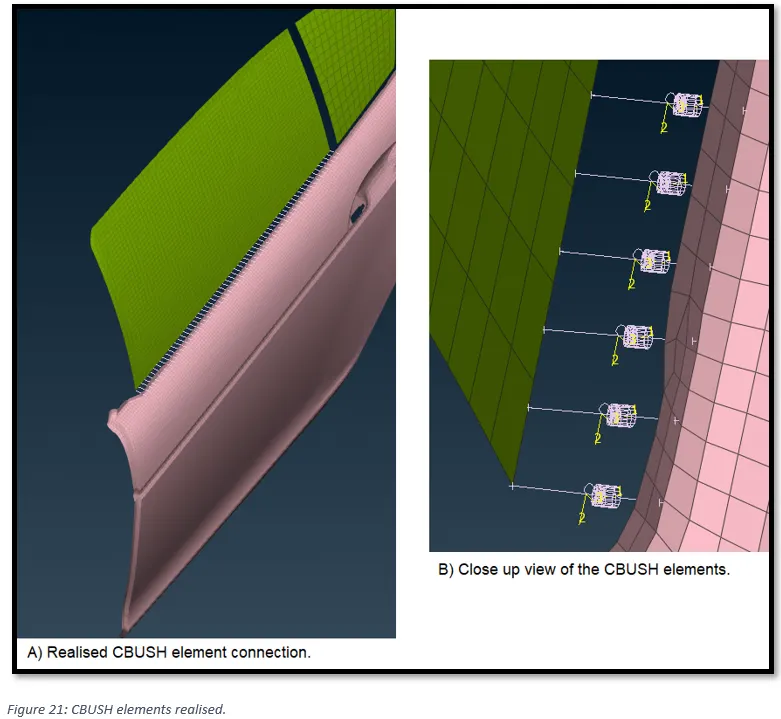
Then go to the connection manage -> select the seam line -> middle click - > Put all the values as shown in the Figure 20 -> select Realize.
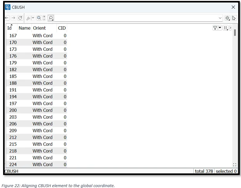
Aligning CBUSH element to the global coordinate.
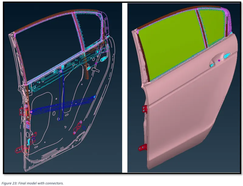
4) Final FE Model with connections.
References:
ANSA_User_Guide
ebook-Practical-Aspects-of-Finite-Element-Simulation (by Altair)
https://skill-lync.com/knowledgebase/common-doubts-in-connections-print