Week-7 Challenge: DC Motor Control
1) A. Speed control of a DC motor using BJT H-bridge.
Simulink Model:
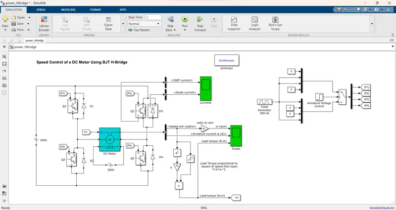
- The Bipolar Junction Transistor (BJT) when used for power-switching applications, operates as an IGBT.
- When it is conducting a forward voltage Vf is developed between the collector and emitter (in the range of 1 V).
- Therefore, the IGBT block can be used to model the BJT device.
DC motor
- The switch is controlled by a Simulink signal (1/0).
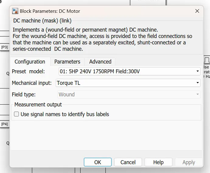
- The DC motor uses the preset model (5 HP 24V 1750 rpm).
- It simulates a fan-type load. The armature means voltage can be varied from 0 to 240 V when the duty cycle is varied from 0 to 100%.
H-bridge
- The H-bridge circuit is used for controlling the DC motor speed and rotating the side to go backward or forward.
- The H-bridge consists of four Diode pairs.
- Two transistors are switched simultaneously: Q1 and Q4 or Q2 and Q3. When Q1 and Q4 are fired, a positive voltage is applied to the motor, and diodes D2-D3 operate as free-wheeling diodes when Q1 and Q4 are switched off. When Q2 and Q3 are fired, a negative voltage is applied to the motor, and diodes D1-D4 operate as free-wheeling diodes when Q2 and Q3 are switched off.
H-Bridge concept
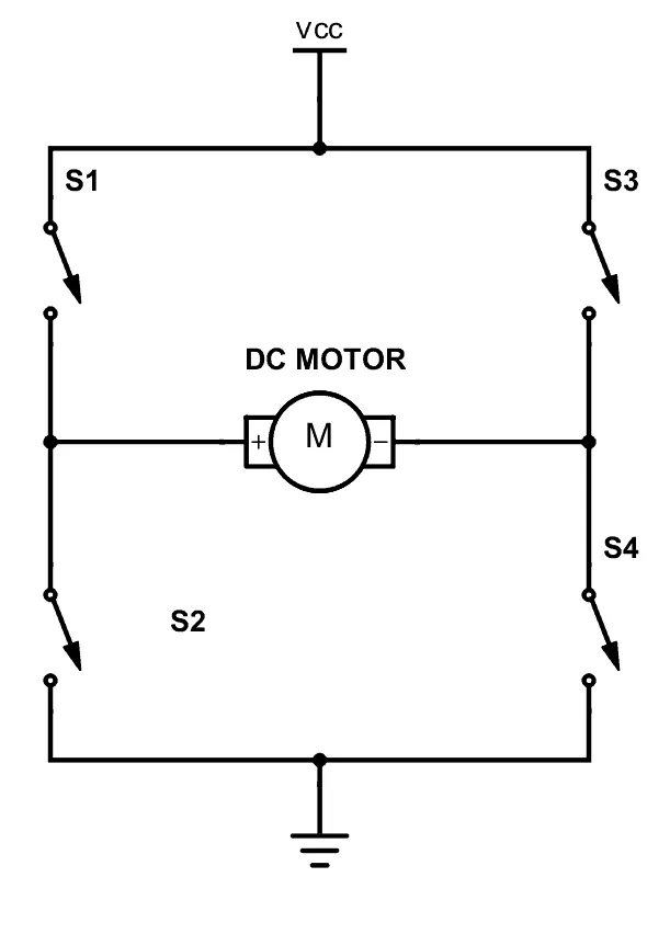
- We can build an H-bridge with four transistors.
- If we close switches 1 and 4, we have plus connected to the left side of the motor and minus to the other side. And the motor will start spinning in one direction.
- If we instead close switches 2 and 3, we have plus connected to the right side and minus to the left side. And the motor spins in the opposite direction.
Output Result
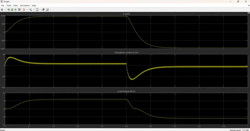
The output graph consists of the speed of the motor, armature current, and load torque of the motor.
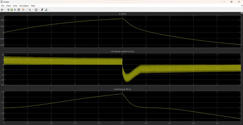
B. Comment on the armature current shoot-up from the scope results.
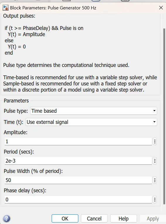
changing duty cycle at 50%.
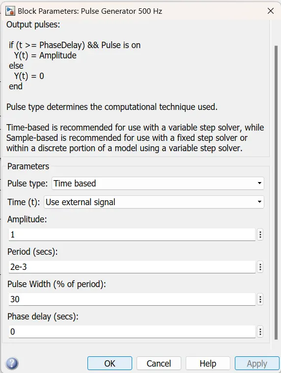
changing duty cycle at 30%
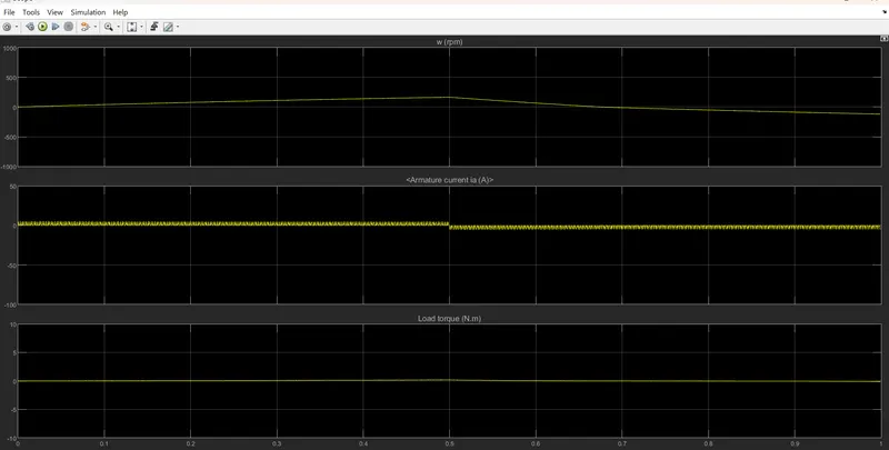
Thus to reduce the shoot-up armature currents we have to change the duty cycle gradually from 0 to 100%, which increases voltage gradually, and speed also changes accordingly.
C. Comparing ‘The Four-Quadrant Chopper DC Drive (DC7) block’ with the H bridge model.
Simulink model of DC7 four-quadrant chopper DC drive.
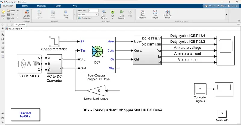
- The 200 HP DC motor is separately excited with a constant 150 V DC field voltage source.
- The converter is fed by a 515 V DC bus obtained by rectification of a 380 V AC 50 Hz voltage source.
- In order to limit the DC bus voltage during dynamic braking mode, a braking chopper has been added between the diode rectifier and the DC7 block.
- The speed regulator outputs the armature current reference used by the current controller in order to obtain the electromagnetic torque needed to reach the desired speed.
- The current regulator controls the armature current by computing the appropriate duty ratios of the 5 kHz pulses of the four IGBT devices.
- The instantaneous pulse values of IGBT devices 1 and 4 are opposite to those of IGBT devices 2 and 3.
- This generates the average armature voltage needed to obtain the desired armature current.
Output Graph
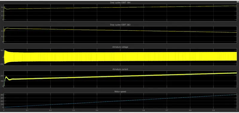
Working Principle of Four-Quadrant DC drive DC7 block
- The Four-Quadrant Chopper DC Drive (DC7) block represents a four-quadrant, DC-supplied, chopper drive for DC motors.
- This drive features closed-loop speed control with the four-quadrant operation.
- The speed control loop outputs the reference armature current of the machine.
- The main advantage of this drive, compared with other DC drives, is that it can operate in all four quadrants.
- A motor operates in two modes – Motoring and Braking. A motor drive capable of operating in both directions of rotation and of producing both motoring and regeneration is called a Four Quadrant variable speed drive.
- In motoring mode, the machine works as a motor and converts the electrical energy into mechanical energy, supporting its motion.
- In braking mode, the machine works as a generator and converts mechanical energy into electrical energy and as a result, it opposes the motion.
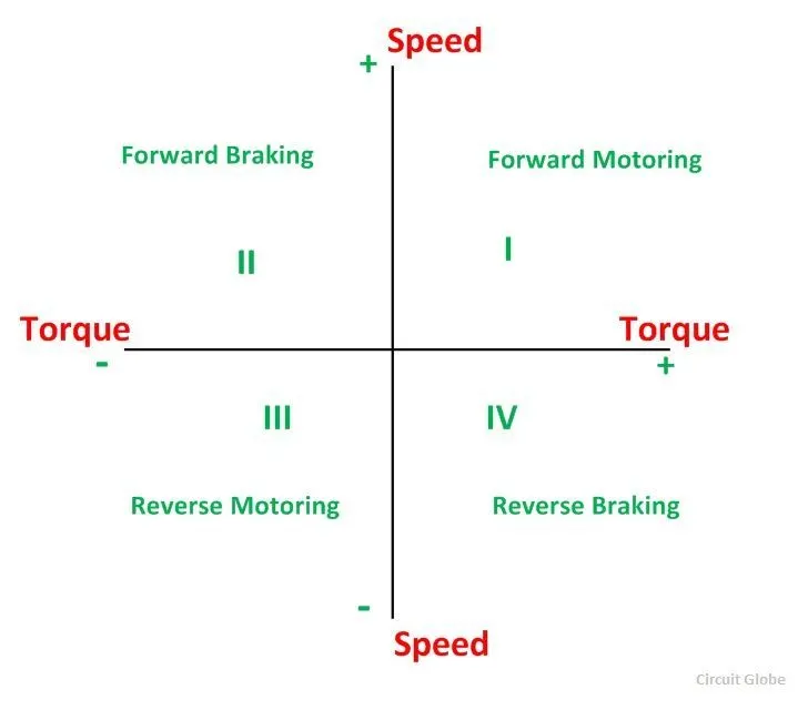
- In the first quadrant, the power developed is positive and the machine is working as a motor supplying mechanical energy. The first quadrant operation is called Forward Motoring.
- In the second quadrant, the direction of rotation is positive, and the torque is negative, thus, the machine operates as a generator developing a negative torque, which opposes the motion.
- In the third quadrant, the operation is known as reverse motoring. The motor works, in the reverse direction. Both the speed and the torque have negative values while the power is positive.
- In the fourth quadrant, the torque is positive, and the speed is negative. This quadrant corresponds to the braking in the reverse motoring mode.
Comparisons of Four-Quadrant chopper DC7 block vs H-bridge model
- The Four-Quadrant Chopper DC7 can operate in all four modes (forward motoring, forward braking, reverse motoring, and reverse braking).
- The H-bridge can operate only in two modes (forward and reverse).
- Regenerative braking is not possible in H-bridge.
- Regenerative braking is possible in chopper it is possible.
- The Four-Quadrant Chopper is generally used in industrial applications.
- The H bridge model is used in robotics.
- In the Four-Quadrant Chopper, a PI regulator is used.
- In the H-bridge model PI regulator is not used.
2) Develop a 2-quadrant chopper using Simulink
Two Quadrant Chopper
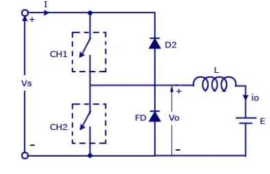
Where,
Vs = DC voltage source.
CH1 = Power electronic switch 1.
CH2 = Power electronic switch 2.
D2, FD = Free wheeling diodes.
L = Inductor load.
E Back emf from the load.
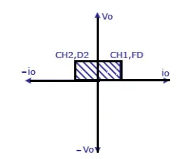
- In this type of Chopper, the average voltage will be always positive but the average load current might be positive or negative.
- The two Switches CH1 and CH2 should not be turned on simultaneously.
- For regenerative braking and motoring, this type of chopper configuration is used.
- We will always get a positive output voltage V0 as the freewheeling diode FD is present across the load.
- When the chopper CH1 is on the current flows from source to load. The inductor stores energy.
- When Ch1 turns OFF the freewheeling diode starts conducting and the output voltage v0 will be equal to Vs.
- The direction of the load current i0 will be reversed.
- The current i0 will be flowing toward the source.
- The load current will be negative when the CH2 is on.
- The current completes its path through diode D2.
Simulink diagram of Two Quadrant Chopper
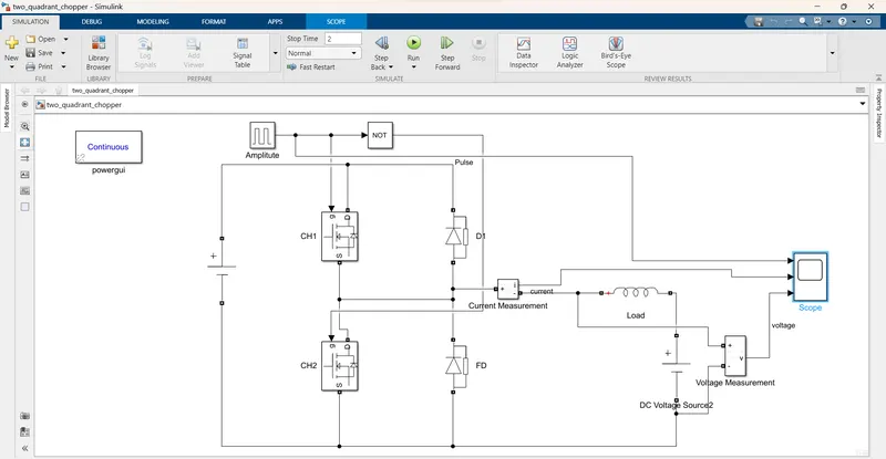
- The given input is 24 v dc supply and given the amplitude is 10 v.
- The inductance is act as the load. The NOT gate is used for switching operations.
Output Graph
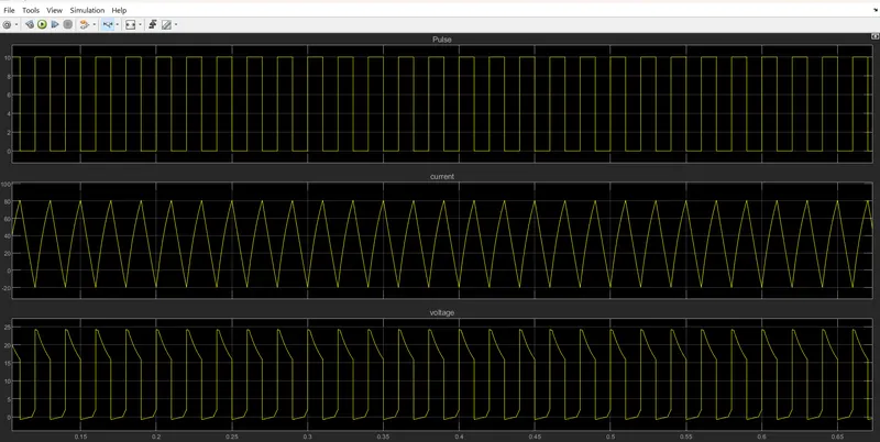
- In voltage waveform shows, it is not going less than zero.
- The minimum value is zero, and the maximum value is positive.
- The current goes positive as well as negative based on the switching action.
3) Operation of BLDC motor
Brushless DC Motors or BLDC Motors
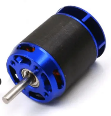
- Brushless DC electric motors are also known as electronically commutated motors (ECMs, EC motors).
- Primary efficiency is the most important feature of BLDC motors.
- Because the rotor is the sole bearer of the magnets and it doesn't require any power.
- That is no connections, no commutator, and no brushes.
Construction of Brushless DC motor
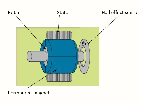
- In this motor, the permanent magnets are attached to the rotor.
- The current-carrying conductors or armature windings are located on the stator.
- They use electrical commutation to convert electrical energy into mechanical energy.
- The main design difference between brushed and brushless motors is the replacement of the mechanical commutator with an electric switch circuit.
- A BLDC Motor is a type of synchronous motor in the sense that the magnetic field generated by the stator and the rotor revolve at the same frequency.
- The Brushless motor does not have any current carrying commutators.
Working Principle of Brushless DC motor
- BLDC motor works on a principle similar to that of a Brushed DC motor.
- The Lorentz force law states that whenever a current-carrying conductor is placed in a magnetic field it experiences a force.
- As a consequence of reaction force, the magnet will experience an equal and opposite force.
- In the BLDC motor, the current-carrying conductor is stationary and the permanent magnet is moving.
- When the stator coils get a supply from the source, it becomes an electromagnet and starts producing the uniform field in the air gap.
- Though the source of supply is DC, switching makes to generate an AC voltage waveform with a trapezoidal shape.
- Due to the force of interaction between the electromagnet stator and permanent magnet rotor, the rotor continues to rotate.
- With the switching of windings as High and Low signals, corresponding winding energized as North and South poles.
- The permanent magnet rotor with North and South poles aligns with the stator poles which causes the motor to rotate.
Advantages of Brushless DC motor
- Higher speed range and lower electric noise generation.
- It has no mechanical commutator and associated problems.
- High speed of operation even in loaded and unloaded conditions due to the absence of brushes that limits the speed.
- Smaller motor geometry and lighter in weight than both brushed-type DC and induction AC motors.
- Higher dynamic response due to low inertia and carrying windings in the stator.
- Less electromagnetic interference.
- Low noise due to the absence of brushes.
Applications of Brushless DC motor
- BLDC is used for a wide variety of application requirements such as varying loads, constant loads, and positioning applications in the fields of industrial control, automotive, aviation, automation systems, and health care equipment.