Week-6 Challenge: EV Drivetrain
1) Power converter circuits employed in electric and hybrid electric vehicles are
Power converter
- A power converter is an electrical circuit that changes the electric energy from one form into the desired form optimized for the specific load.
- A converter may do one or more functions and give an output that differs from the input.
- It is used to increase or decrease the magnitude of the input voltage or produce several output voltages.
The Power Electronic Converter can be classified into :
- AC to DC Converter (Controlled Rectifier)
- DC to DC Converter (DC Chopper)
- AC to AC Converter (AC voltage regulator)
- DC to AC Converter (Inverter)
AC to DC Converters
- That converts the AC signal into a DC signal known as a rectifier.

AC to DC Converter is further classified as:
- Diode Rectifiers: This rectifier circuit changes the applied ac input voltage into a fixed dc voltage. Either a single-phase or three-phase ac signal is applied at the input. These are mainly used in electric traction and in electrochemical processes like electroplating along with battery charging and power supply.
- Phase-Controlled Rectifiers: Phase-controlled rectifiers are designed to convert a fixed value of ac signal voltage into a variable dc voltage. Here line voltage operates the rectifier hence these are sometimes known as line commutated ac to dc converters. Similar to diode rectifiers, here also the applied ac signal can be a single-phase or three-phase ac signal. Its major applications are in dc drives, HVDC systems, compensators, and excitation systems for synchronous machines.
DC to DC Converters
- The converters that convert the dc signal of fixed frequency present at the input into a variable dc signal at the output are also known as choppers.
- Here the achieved output dc voltage may have a different amplitude than the source voltage.
- Generally, power transistors, MOSFETs, and thyristors are the semiconductor devices used for their fabrication.
- Choppers are classified on the basis of the type of commutation applied to them and on the basis of the direction of power flow.
- Some major uses of choppers are in dc drives, SMPS, electric traction, trolley trucks, vehicles powered by battery, etc.

DC to AC Converters
- The devices that are designed to convert the dc signal into ac signal are known as inverters.
- The applied input is a fixed dc voltage that can be obtained from batteries but the output obtained is a variable ac voltage. The voltage and frequency of the signal obtained are of variable nature.
- Here the semiconductor device i.e., the thyristor is turned off by using either line, load, or forced commutation.
- Thus, it can be said that by the use of inverters, a fixed dc voltage is changed into an ac voltage of variable frequency.
- Inverters mainly find applications in induction motors and synchronous motor drives along with UPS, aircraft, and space power supplies.

AC to AC Converters
- An ac to ac converter is designed to change the ac signal of fixed frequency into a variable ac output voltage.

There are two classifications of AC to AC Converters which are as follows:
- Cycloconverters: A cycloconverter is a device used for changing ac supply of fixed voltage and single frequency into an ac output voltage of variable voltage as well as different frequency. However, here the obtained variable ac signal frequency is lower than the frequency of the applied ac input signal. It adopts single-stage conversion.
These mainly find applications in slow-speed large AC traction drives such as multi-MW ac motor drives, etc.
- AC Voltage regulators: The converters are designed to change the applied ac signal of fixed voltage into a variable ac voltage signal of the same frequency as that of input. For the operation of these controllers, two thyristors in an antiparallel arrangement are used. Line commutation is used for turning off both devices. It offers the controlling of the output voltage by changing the firing angle delay.
The major applications of ac voltage controllers are in lighting control, electronic tap changers, and speed control of large fans and pumps as well.
2) An Electric Vehicle's powertrain with a 72V battery pack is shown in the diagram below. The duty ratio for the acceleration operation is 'd1' and for the braking operation the duty ratio is 'd2'.
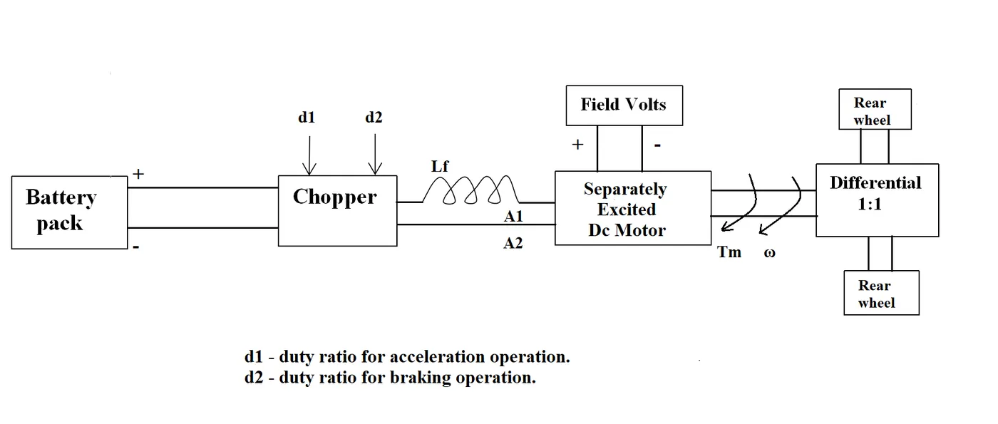
The other parameters of the electric vehicle are given below,
Motor and Controller Parameters:
Rated Armature voltage= 72 V
Rated armature current= 400 A
Ra= 0.5Ω, KΦ= 0.7 Volt second
Chopper Switching frequency= 400 Hz
The vehicle speed-torque characteristics are given by the below equation

What is EV steady state speed if the duty cycle is 70%?
Given Parameters:
Battery pack voltage (V) = 72 V
Rated armature current = 400 A
Armature Resistance (Ra) = 0.5 Ω
Motor constant (KΦ) = 0.7
Chopper Switching frequency= 400 Hz
Duty Cycle = 70%
Solution :
The vehicle speed-torque characteristics equation is
T = 24.7+(0.0051)w2 ---equation(1)
Duty cycle = 70% = 0.7
Vehicle Output Voltage = Battery Voltage(V)*Duty Cycle
= (72*0.7) = 50.4 V
The vehicle Output voltage is = 50.4 V
We have a torque equation for the motor,
T = (V*kϕ/Ra) − ((kϕ)^2/Ra)⋅w
Where;
T = Vehicle Torque (N-m)
V = Vehicle voltage (Volts)
w = steady state speed of the vehicle
K∅ = Motor constant
Ra= Armature Resistance
T = (50.4*0.7)/(0.5) − ((0.7)^2/0.5)⋅w
T = 70.56 − 0.98⋅w -----equation(2)
Solving these two equations 1&2
24.7 + 0.0051⋅w^2 = 70.56 − 0.98⋅w
0.0051w^2 + 0.98w - 70.56 + 24.7 = 0
0.0051w^2 + 0.98w − 45.86 = 0
by solving this equation by quadratic equation we get,
ax² + bx + c = 0
x = w
x =−b±√(b^2−4ac)/(2a)
x = (−0.98 ± √(0.98)^2−4*(0.0051)*(−45.86)) / (2*0.0051))
w = 38.74 rad/s
Steady-state speed of vehicle = 38.74 rad/s.
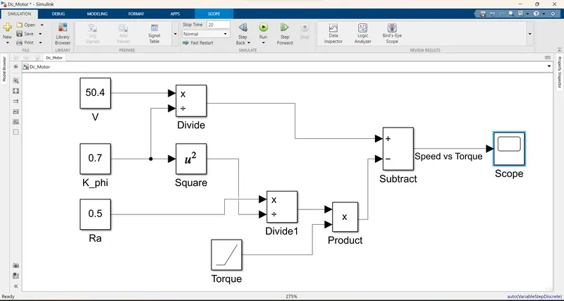
3) Develop a mathematical model of a DC Motor for the below equation using Simulink.
ω = V/Kϕ - Ra/Kϕ^2 .T
V = 50.4 v
K∅ = 0.7
Ra = 0.5 Ω
T = linearly increasing
Simulink Model
Output Graph
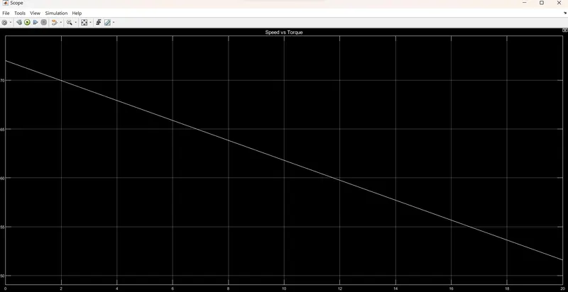
The speed is determined with a help of a mathematical model in Simulink, By using the given formula.
4) Induction Versus DC Brushless Motors
A brief about the author’s perspective is :
- Wally Rippel is a long-time proponent of electric vehicles.
- Prior to joining Tesla Motors, he was an engineer at AeroVironment.
- where he helped develop the EV1 for General Motors and was featured in the documentary movie, Who Killed the Electric Car?
- Wally has also worked for the Jet Propulsion Laboratory on electric vehicle battery research, among other projects.
- In 1968, as a Caltech undergraduate student, he built an electric car and won the Great Transcontinental Electric Car Race against MIT.
- He carried a slide rule, there were lead acid batteries, DC brush motors, and contactor controllers.
- It has been replaced by lithium and DC by either DC brushless or induction.
- He guesses both induction and brushless machines “duke it out” for many years to come.
- In brushless machines, the rotor includes two or more permanent magnets that generate a DC magnetic field.
- A forerunner of the 3-phase induction motor was invented by Nikola Tesla sometime before 1889.
- The fact that induction motors are directly compatible with conventional utility power is the main reason for their success.
Brushless or Induction
- Back in the 1990s all of the electric vehicles except one were powered by DC brushless drives.
- Today, all the hybrids are powered by DC brushless drives, with no exceptions.
- Both DC brushless and induction drives use motors having similar stators.
- Both drives use 3-phase modulating inverters.
- The only differences are the rotors and the inverter controls.
DC Brushless
- Less rotor heat is generated with the DC brushless drive.
- Rotor cooling is easier and peak point efficiency is generally higher for this drive.
- The DC brushless drive can also operate at a unity power factor, whereas the best power factor for the induction drive is about 85 percent.
- This means that the peak point energy efficiency for a DC brushless drive will typically be a few percentage points higher than for an induction drive.
Induction Motor
- In induction, machines have no magnets, and B fields are adjustable since B is proportionate to V/f (voltage to frequency).
- This means that at light loads the inverter can reduce voltage such that magnetic losses are reduced and efficiency is maximized.
- Thus, the induction machine when operated with a smart inverter has an advantage over a DC brushless machine.
- This advantage becomes increasingly important as performance is increased.
Thus, induction drives may be the favored approach where high performance is desired; peak efficiency will be a little less than with DC brushless, but average efficiency may actually be better. - Induction machines are more difficult to control. The control laws are more complex and difficult to understand.
- Achieving stability over the entire torque-speed range and over temperature is more difficult with induction than with DC brushless.
He says "Still No Winner", is that DC brushless drives will likely continue to dominate in the hybrid and coming plug-in hybrid markets, and that induction drives will likely maintain dominance for the high-performance pure electrics.
CONCLUSION
- We discussed different types of power converter circuits employed in electric and hybrid electric vehicles.
- We get EV steady state speed of an EV Drivetrain was determined with the given inputs conditions.
- The Mathematical model for the DC motor is developed and created in the Simulink model in Simulink.
- we provide explain in brief about the author’s perspective on DC brushless motors and induction motors.