Project - Speed Control of a Direct Current (DC) motor
1) Mathematical modeling
w(s)/Vs(s) = Kt/((J*La*s^2)+(J*Ra+B*La)*s+(B*Ra+kt*km))
2) Simulink-based modeling
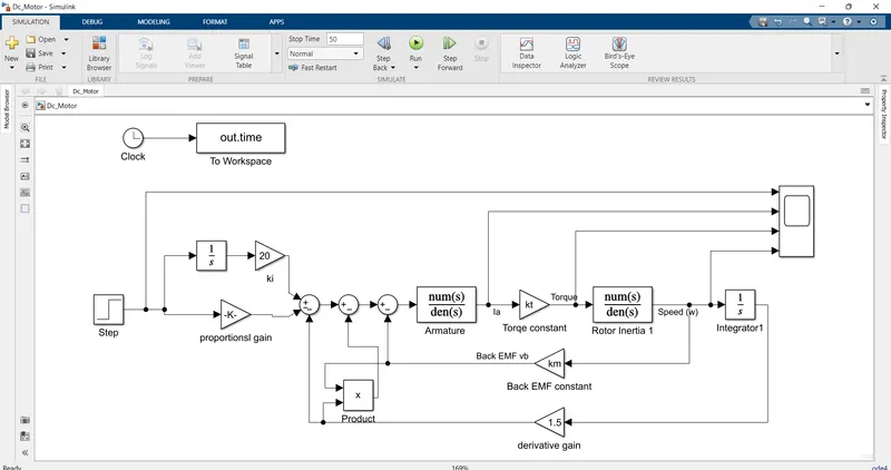
3) Control law design and test parameters.
J = 0.01; % Moment of inertia the rotor in kg-m^2
b = 0.1; % Motor viscous friction constant in N-m-s
km = 0.01; % Back EMF constant in v/rad/s
kt = 0.01; % Motor torque constant in N-m/amp
Ra = 1.0; % Resistance of the armature circuit in ohms
La = 0.5; % Inductance of the armature circuit in henries
wn = 6.2832; % sqrt (k/m)rad/s
fn = 1.0; % wn/(2*pi)Hz
zeta = 0.6; % under damped system
p1 = -zeta*wn+wn*sqrt(zeta^2-1);
p2 = -zeta*wn-wn*sqrt(zeta^2-1);
P = [p1;p2];
% A & B matrices
A = [-92.1811 -10.5350;57.7878 -0.1333];
B = [8.2305;0];
% pole placement design
K = place(A,B,P);
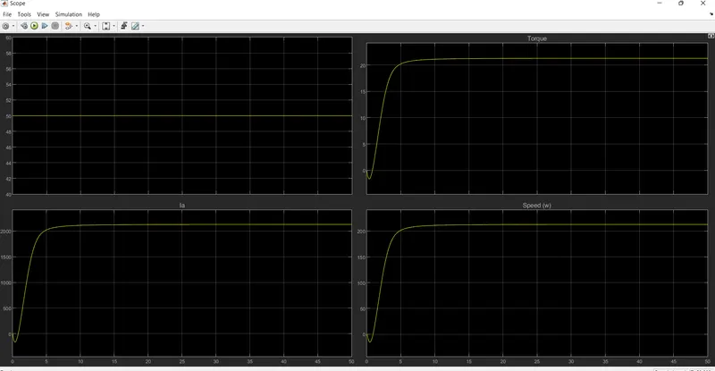
Output Graph
Description
1) The DC motor is developed.
2) The Proportional, Integral, and Derivative (PID) gains are developed.
3) To control to maintain a desired speed for the motor.
4) The output was verified.