Week-7 Challenge: DC Motor Control
1. Speed control of a DC motor using BJT H-bridge
In a power switching application, BJT operates as an IGBT at the Vce collector-emitter voltage ranging as 1v. So BJT is replaced by IGBT in the model.
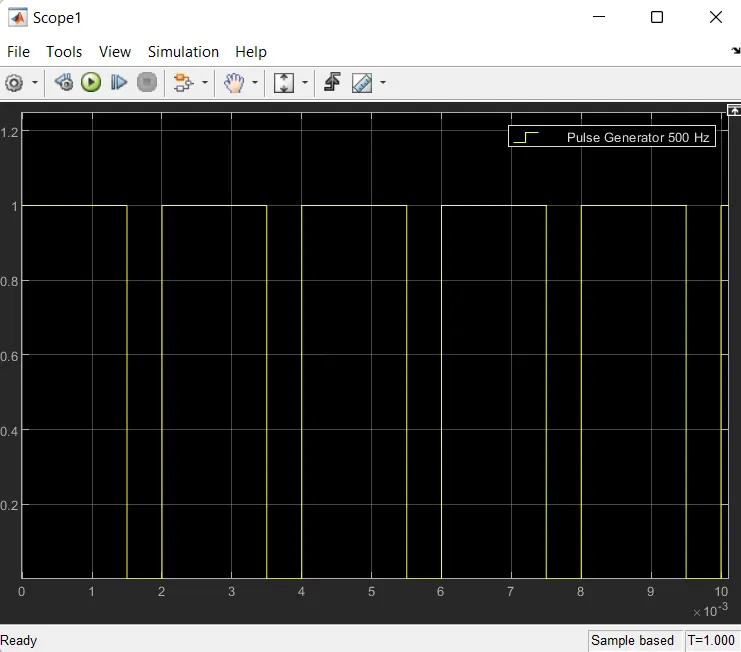
The Gate current (switch) is controlled by a PWM signal from the pulse generator of 500hz.
The total period is 1sec.
Frequency 500Hz and the period of 2ms i.e 1/freq= time=1/500.
75% of duty cycle, so Ton is 1.5ms.
PWM Signal showed in the following figure
In an H-bridge BJT converter is used to control the speed of the dc motor. The shape of the converter looks like H alphabetic letter so it is named as BJT H-bridge converter.
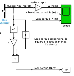
The DC motor uses the preset model (5 HP 240V 1750 rpm). It simulates a fan-type load (where Load torque is proportional to the square of speed). The armature means voltage can be varied from 0 to 240 V when the duty cycle (specified in the Pulse Generator block) is varied from 0 to 100%.
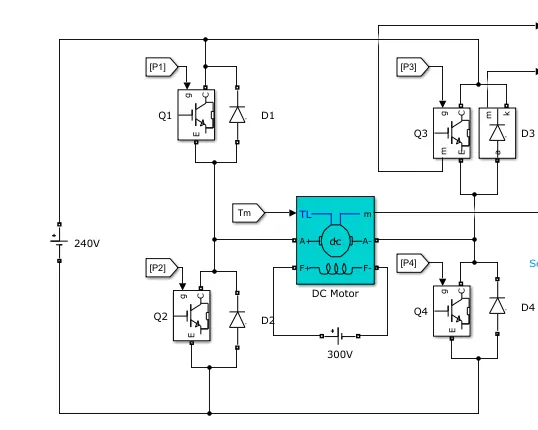
The H-bridge consists of four BJT/Diode pairs (BJT simulated by IGBT models). Two transistors are switched simultaneously: Q1 and Q4 or Q2 and Q3. When Q1 and Q4 are fired, a positive voltage is applied to the motor, and diodes D2-D3 operate as free-wheeling diodes when Q1 and Q4 are switched off. When Q2 and Q3 are fired, a negative voltage is applied to the motor, and diodes D1-D4 operate as free-wheeling diodes when Q2 and Q3 are switched off.
Pulse Generator 500Hz
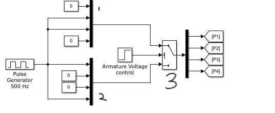
Explanation of triggering circuit.
- State 1. Q1 and Q4 are 0, and Q2 and Q3 are 75% duty cycle pulse given. After 0.5-sec armature voltage is negative and the motor is in the reverse direction. (Q2, Q3, D1, and D4 are conducted)
- State 2. Q2 and Q3 are 0, and Q1 and Q4 are 75% duty cycle pulse given. i.e up to 0.5-sec armature voltage is positive and motor in forwarding direction. (Q1, Q4, D2, and D3 are conducted)
- Armature voltage control state 2 operates till 0.5 sec then state 1 operates
'Scope' shows motor speed, armature current, and load torque and 'Currents' shows currents flowing in BJT Q3 and diode D3.
Fan Torque equation T=k*w^2
K constant value is 6.062e-4=0.0006062
Output
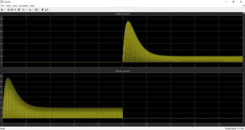
The above graph clearly shows that till 0.5 secs D3 Diode conducting after 0.5 sec Q3 conducting(i.e. Diode current value changed from zero.
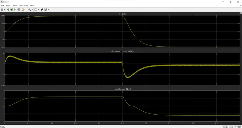
At t<0.5 sec, the motor is in a forward direction and the armature current is in a positive.
Fan load Torque in Positive value.
At t>= 0.5 sec., the armature voltage is suddenly reversed so the armature current is in the negative and the motor runs in the negative direction.
The load torque started to decrease and reaches its negative value.
1. b. Armature current shoot-up (Starting current) to rotate the rotor every time the motor is run from a stop condition. It is also called Inrush Current or Lock Rotor Current (LRC) where the value can reach 6 or 7 times of operating current if starting with the Direct On-Line (DOL) method, and can also be less than depending on the design.
Starting Current takes place for a few seconds. After reaching 75% of the rated speed the Starting current gets reduced to nominal current or rated current or operating current
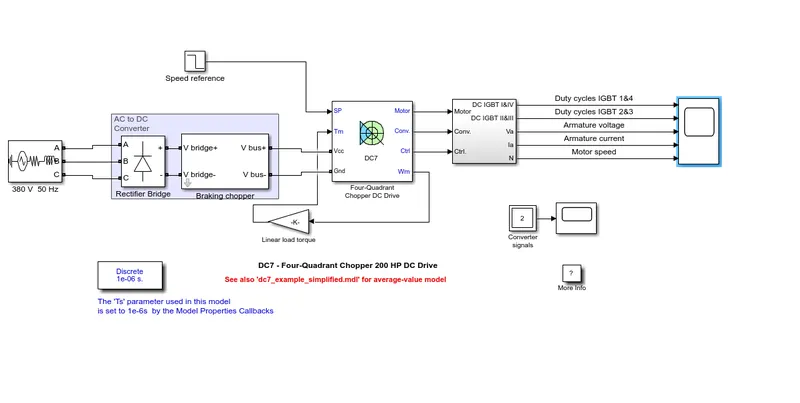
1. c) The Four-Quadrant Chopper DC Drive (DC7) block
Description
The 200 HP DC motor is separately excited with a constant 150 V DC field voltage source. The armature voltage is provided by an IGBT converter controlled by two PI regulators. The converter is fed by a 515 V DC bus obtained by rectification of a 380 V AC 50 Hz voltage source. To limit the DC bus voltage during dynamic braking mode, a braking chopper has been added between the diode rectifier and the DC7 block.
The first regulator is a speed regulator, followed by a current regulator. The speed regulator outputs the armature current reference (in p.u.) used by the current controller to obtain the electromagnetic torque needed to reach the desired speed. The speed reference change rate follows acceleration and deceleration ramps to avoid sudden reference changes that could cause armature over-current and destabilize the system. The current regulator controls the armature current by computing the appropriate duty ratios of the 5 kHz pulses of the four IGBT devices (Pulse Width Modulation). For proper system behavior, the instantaneous pulse values of IGBT devices 1 and 4 are opposite to those of IGBT devices 2 and 3. This generates the average armature voltage needed to obtain the desired armature current. To limit the amplitude of the current oscillations, a smoothing inductance is placed in series with the armature circuit.
Simulation
Before starting the simulation, set the initial bus voltage to 515 V via the GUI block ('The Initial States Setting' button and 'Cbus' variable).
Start the simulation. You can observe the motor armature voltage and current, the four IGBT pulses, and the motor speed on the scope. The current and speed references are also shown.
The motor is coupled to a linear load, which means that the mechanical torque of the load is proportional to the speed.
The speed reference is set at 500 rpm at t = 0 s. Observe that the motor speed follows the reference ramp accurately (+400 rpm/s) and reaches a steady-state around t = 1.3 s.
The armature current follows the current reference very well, with a fast response time and small ripples. Notice that the current ripple frequency is 5 kHz.
At t = 2 s, the speed reference drops to -1184 rpm. The current reference decreases to reduce the electromagnetic torque and causes the motor to decelerate with the help of the load torque.
At t = 2.2 s, the current reverses to produce a braking electromagnetic torque (dynamic braking mode). This causes the DC bus voltage to increase.
At t = 3.25 s, the motor reaches 0 rpm and the load torque reverses and becomes negative. The negative current now produces an accelerating electromagnetic torque to allow the motor to follow the negative speed ramp (-400 rpm/s). At t = 6.3 s, the speed reaches -1184 rpm and stabilizes around its reference.
Note
- The power system has been discretized with a 1 us time step. The speed and current controllers use a 100 us and 20 us sampling time respectively to simulate a microcontroller control device.
- To reduce the number of points scored in the scope memory, a decimation factor of 25 is used. Some transitions may thus not appear on the scope. To view detailed simulation results, reduce the decimation factor to 1.
- A simplified version of the model using an average-value converter can be used by selecting 'Average' in the 'Model detail level' menu of the graphical user interface. The time step can then be increased up to the smallest control system sample time value. This can be done by typing 'Ts = 20e-6' in the workspace in the case of this example.
- The microcontroller is used to control the four-quadrant chopper and in the H bridge, switches are controlled by the PWM technique.
- Four-quadrant chopper dc7 is faster in operation when compared to the H bridge.
2. Two quadrant chopper
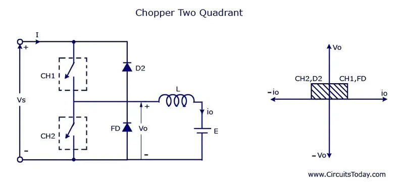
The above image shows the two-quadrant chopper.
Forward motoring mode (1st quadrant) Load Voltage and load current are positive. In this quadrant, ch1 and FD switches are closed(ON condition)(respectively IGBT and diode). When ch1 is on the current flows from the source to load. The inductor stores energy. Current flow as
Vs(+ve) -> Ch1 ->L -> Motor ->Vs(-ve)
Motor consume the power from source
When ch1 is open(turned OFF) freewheeling diode (FD) starts conducting and the output voltage vo will be equal to vs. Load current will be reversed. Stored energy discharged as
L -> Motor -> FD ->L
Forward Breaking mode(2nd quadrant). ch2 and d2 will be turned ON. The load current is negative and the load voltage is positive. Ch2 is on then the circuit closed as
Motor -> L -> Ch2 -> Motor .
when ch2 is off then the circuit closed as the supply
Vs(-ve) -> Motor -> L -> D2 -> Vs(+ve)
motor fed back the power to the source.
The Gate current (switch) is controlled by a PWM signal from the pulse generator of 100hz.
The total period is 1sec, the Frequency 100Hz, and the time period of 10ms i.e 1/freq= time=1/100
90% of duty cycle so Ton is 9ms
PWM Signal showed in the following figure:
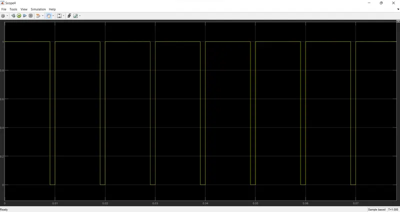
Pulse generator 100hz
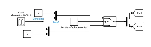
Before 0.5 sec ch1 chopper is turned on with 90% of duty cycle
ch2 chopper is turned off
After 0.5-sec Chopper ch2 is turned on with 90% of the duty cycle and ch1 chopper is turned off.
Fan torque load is already explained.
Output
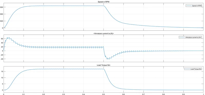
0 to 0.5 Sec Motoring mode, Speed, Armature current, Load torque is Positive.
0.5 to 1 Sec regenerative mode(Braking). Speed is decreased from its rated speed to Stand still. Armature current in the negative valve.
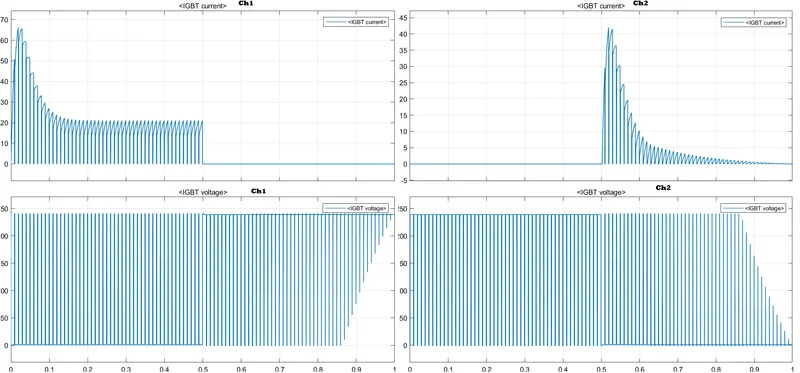
Fig: Ch1 and Ch2 Chopper current and voltage graph.
Ch1 chopper is turned on in motoring mode and turned off in braking mode.
Ch2 chopper is turned on in braking mode and turned off in motoring mode.
3. BLDC motor
Brushless DC motor operated in DC supply through an electronic commutator.
Construction
The stator has three-phase winding in a distributed manner.
The rotor is a permanent magnet.
Stator current will exert a force on a rotor to rotate at a particular speed. The speed of the BLDC motor is controlled by controlling the stator current.
Stator winding is driven by 3 phase inverter.
BLDC motor consists of a rotor position sensor that produces an electrical signal that indicates the current position of the rotor.
Feedback from the rotor position sensor is given to the inverter circuit. As per the rotor position, the inverter excites the winding of the stator to the rotor at a particular speed.
Rotor speed is controlled by stator current. Stator current is controlled by stator voltage. Stator voltage is controlled by the DC input voltage of the inverter.
Operation of BLDC Motor
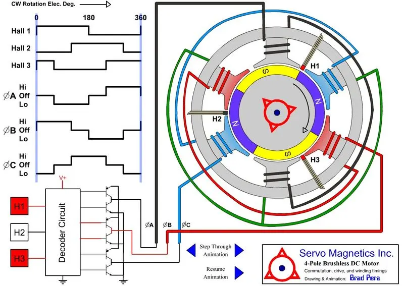
Fig 4-Pole Brushless DC Motor
The stator is 6 Pole distributed winding and the rotor is 4 poles permanent magnet.
Mechanical rotation degree = 2*electrical degree
180 degree=360 degrees in electrical, total rotor has 720 electrical degrees.
720/4pole gives each pole of the rotor 180 electrical degrees.
H1, H2, and H3 are hall effect sensor. which senses the rotor and gets activated when they senses the rotor's south pole.
Note degree is in electrical
H1 in on state till 180 because it senses s pole of the rotor after that it goes to off state till 360
H2 in the off state till 120 after that it goes to on state till 300
H3 is in on state till 60 degrees after that it goes to off state till 240 degrees.
From 0 to 60 degrees: H1 and H3 are activated then Phase B is positive with respect to C(i.e phase c is negative ) and phase an is off condition.
From 60 to 120 degrees: H1 in on state which triggers the inverter circuit as give the Positive supply to b phase with respect to a phase and phase c in off state.
From 120 to 180 degrees: H1 and H2 in the on the state which triggers the inverter circuit to give a positive supply to the C- phase with respect to A-phase and phase B in the off state.
From 180 to 240 degrees: H2 in the on the state which triggers the inverter circuit to give a Positive supply to the C phase with respect to the B phase and phase A in the off state.
From 240 to 300 degrees: H2 and H3 are in an on the state which triggers the inverter circuit to give a Positive supply to A- phase with respect to the B-phase and phase c in the off state.
From 300 to 360 degrees: H3 in the on the state which triggers the inverter circuit to give Positive supply to A-phase with respect to C-phase and phase b in the off state.
further degree repeated sequentially.
Advantages
The heat and noises produced by the machine are low. Because there is no brush for commutation.
Disadvantage
High cost due to permanent magnet.