Week-7 Challenge: DC Motor Control
EV live batch 17
ANS:1
A}
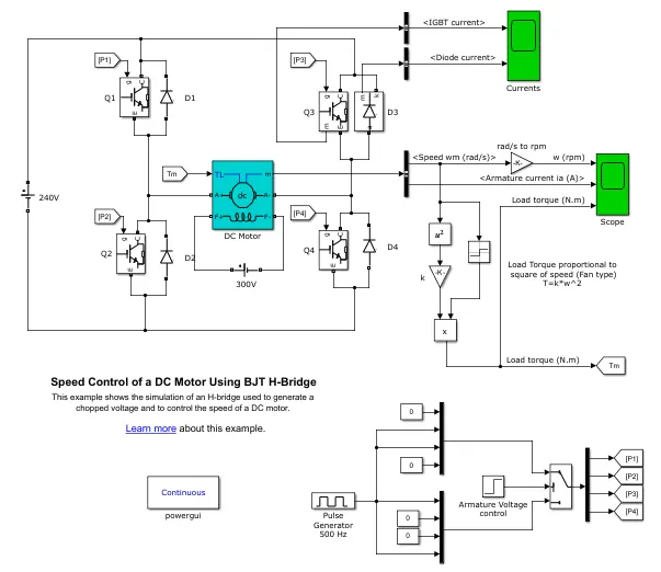
This model consists of H-bridge made of BJT, DC motor. A BJT is used to run the motor in both the direction and to produced chopped voltage as per speed requirement.
The Gate signals to the Q1,Q2,Q3,Q4 is given by pulse generator whose amplitude and frequency is controlled as per armatuere voltage control source.
The motor speed is controlled through armature control operation. The DC motor used is seperately excited DC motor and 300V is given to field winding of motor.
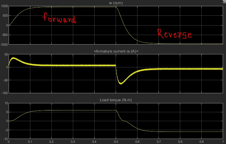
For 0.5 sec motor runs in forward directon and for next 0.5 sec motor runs in reverse direction.
During forward direction , positive current flows through machine as Q1 and Q4 turned ON, during reverse direction Q3 and Q2 turned ON.
B}
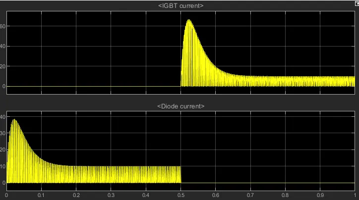
1. From the above results it can be seen that at the start of forward motoring operation of motor, current shoots up and then it stabalized as the speed increased. This is due the fact that at starting condition as the rotor speed is zero or very low, there is no back emf available which causes full rated supply voltage applied across armature winding and due to that high currents flows at starting. This current will low down as speed increses since at higher speed back emf starts increasing.
2. During reversing mode aslo it can be seen that current shoots up. As discusses in point 1, at low speed back emf is low and therefore current is high.
3. It can also be seen that magnitude of shoot up current during reverse is more than forward operation. This is due the fact that when commutation happen i.e reverse operation starts due to sudden change in current from positive to negative direction in very very less time gives high di/dt which causes spikes in current.
C}
Description
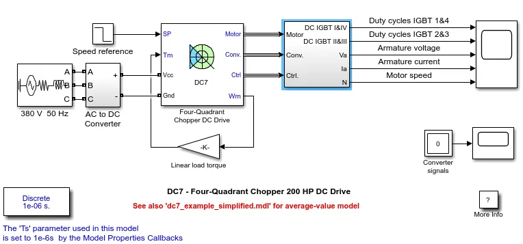
The 200 HP DC motor is separately excited with a constant 150 V DC field voltage source. The armature voltage is provided by an IGBT converter controlled by two PI regulators. The converter is fed by a 515 V DC bus obtained by rectification of a 380 V AC 50 Hz voltage source. In order to limit the DC bus voltage during dynamic braking mode, a braking chopper has been added between the diode rectifier and the DC7 block.
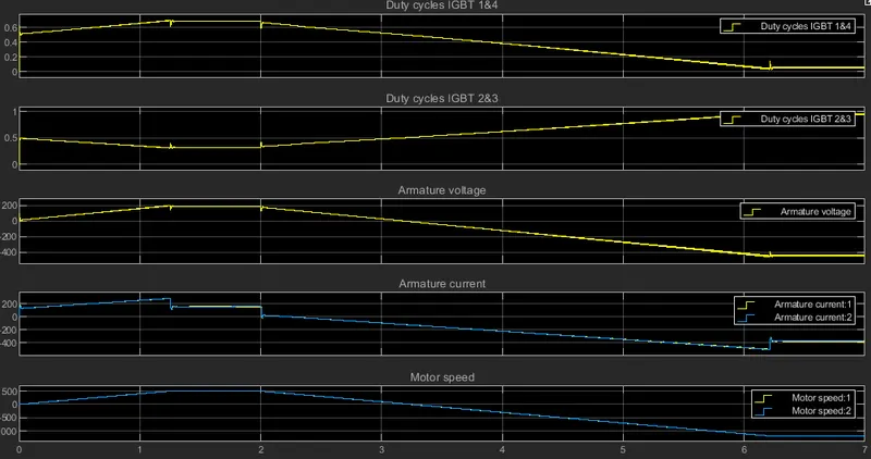
The first regulator is a speed regulator, followed by a current regulator. The speed regulator outputs the armature current reference (in p.u.) used by the current controller in order to obtain the electromagnetic torque needed to reach the desired speed. The speed reference change rate follows acceleration and deceleration ramps in order to avoid sudden reference changes that could cause armature over-current and destabilize the system. The current regulator controls the armature current by computing the appropriate duty ratios of the 5 kHz pulses of the four IGBT devices (Pulse Width Modulation). For proper system behaviour, the instantaneous pulse values of IGBT devices 1 and 4 are opposite to those of IGBT devices 2 and 3. This generates the average armature voltage needed to obtain the desired armature current. In order to limit the amplitude of the current oscillations, a smoothing inductance is placed in series with the armature circuit.
Simulation
1.Before starting the simulation, set the initial bus voltage to 515 V via the GUI block ('Initial States Setting' button and 'Cbus' variable).
2.Start the simulation. You can observe the motor armature voltage and current, the four IGBT pulses and the motor speed on the scope. The current and speed references are also shown.
3.The motor is coupled to a linear load, which means that the mechanical torque of the load is proportional to the speed.
4.The speed reference is set at 500 rpm at t = 0 s. Observe that the motor speed follows the reference ramp accurately (+400 rpm/s) and reaches steady state around t = 1.3 s.
5.The armature current follows the current reference very well, with fast response time and small ripples. Notice that the current ripple frequency is 5 kHz.
6.At t = 2 s, speed reference drops to -1184 rpm. The current reference decreases to reduce the electromagnetic torque and causes the motor to decelerate with the help of the load torque.
7.At t = 2.2 s, the current reverses in order to produce a braking electromagnetic torque (dynamic braking mode). This causes the DC bus voltage to increase.
8.At t = 3.25 s, the motor reaches 0 rpm and the load torque reverses and becomes negative. The negative current now produces an accelerating electromagnetic torque to allow the motor to follow the negative speed ramp (-400 rpm/s). At t = 6.3 s, the speed reaches -1184 rpm and stabilizes around its reference.
Comparison
1. Four quadrant chopper operates in 4 modes i.e Forward motoring, forward braking, reverse motoring, reverse braking. where as H-bridge operates in 2 modes only forward and reverse motoring
2. in 4 quadrant operation regenerative braking is possible , but in H-bridge it is not possible
3. In 4 quadrant chopper two PI controller is used to developed the desires electromagnetic torque to reach the desired speed, control and stabalized the armature current. In H-bridge PI controller is not used.
4.To hcange the direction of rotation current signals are interrupted with one another, in H bridge reverse polarity is applied
5. H-bridge is used in mainly robotics application to forward and reverse. 4 quadrant chopper used in many electronic devices to control power and in automobile application to control speed and torque of motor.
ANS:2
Two quadrant chopper
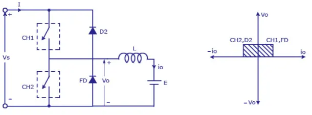
We will always get a positive output voltage V0 as the freewheeling diode FD is present across the load. When the chopper is on the freewheeling diode starts conducting and the output voltage v0 will be equal to Vs . The direction of the load current i0 will be reversed. The current i0 will be flowing towards the source and it will be positive regardless the chopper is on or the FD conducts. The load current will be negative if the chopper is or the diode D2 conducts. We can say the chopper and FD operate together as type-A chopper in first quadrant. In the second quadrant, the chopper and D2 will operate together as type –B chopper.
The average voltage will be always positive but the average load current might be positive or negative. The power flow may be life the first quadrant operation ie from source to load or from load to source like the second quadrant operation. The two choppers should not be turned on simultaneously as the combined action my cause a short circuit in supply lines. For regenerative braking and motoring these type of chopper configuration is used.
Simulink Model
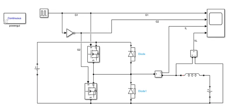
1. MOSFET are used as switch
2. Diodes are used for Freewheeling purpose.
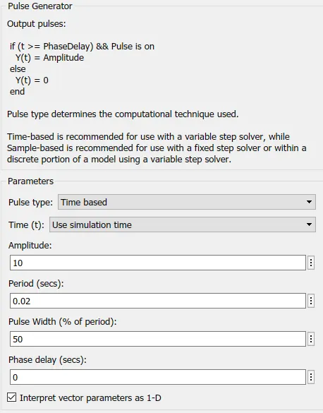
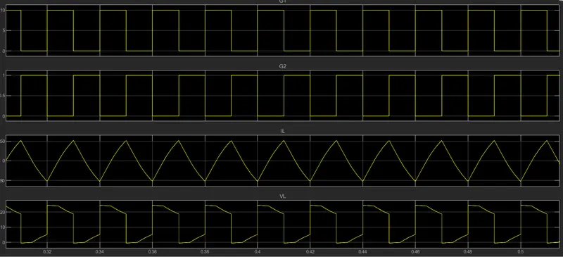
3. Gate pulses to mosfet is is give by gate pulse generator in which amplitude is kept at 10 and period is 0.02 sec. Pulse width is kept as 50%
4. The series parallel branch is used as load in which only inductor is selected.
5. The source side dc voltage is kept as 24V and load side is kept as 12V.
6. Scope is used to see the results.
Results
1. Load voltage is always positive as in case of 2 quadrant chopper
2. Current rises from negative to positive value.
ANS:3
BLDC MOTOR OPERATION
A brushless DC motor (known as BLDC) is a permanent magnet synchronous electric motor which is driven by direct current (DC) electricity and it accomplishes electronically controlled commutation system (commutation is the process of producing rotational torque in the motor by changing phase currents through it at appropriate times) instead of a mechanically commutation system. BLDC motors are also referred as trapezoidal permanent magnet motors.
BLDC motor works on the principle similar to that of a conventional DC motor, i.e., the Lorentz force law which states that whenever a current carrying conductor placed in a magnetic field it experiences a force. As a consequence of reaction force, the magnet will experience an equal and opposite force. In case BLDC motor, the current carrying conductor is stationary while the permanent magnet moves.
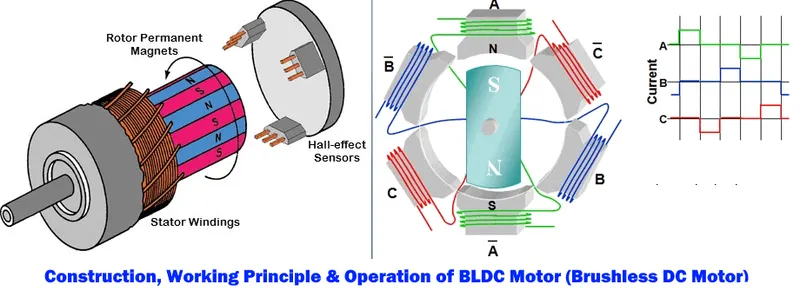
When the stator coils are electrically switched by a supply source, it becomes electromagnet and starts producing the uniform field in the air gap. Though the source of supply is DC, switching makes to generate an AC voltage waveform with trapezoidal shape. Due to the force of interaction between electromagnet stator and permanent magnet rotor, the rotor continues to rotate.
Consider the figure below in which motor stator is excited based on different switching states. With the switching of windings as High and Low signals, corresponding winding energized as North and South poles. The permanent magnet rotor with North and South poles align with stator poles causing motor to rotate.
Observe that motor produces torque because of the development of attraction forces (when North-South or South-North alignment) and repulsion forces (when North-North or South-South alignment). By this way motor moves in a clockwise direction.
which stator coil should be energized and when is because; the motor continuous rotation depends on the switching sequence around the coils. As discussed above that Hall sensors give shaft position feedback to the electronic controller unit.
Based on this signal from sensor, the controller decides particular coils to energize. Hall-effect sensors generate Low and High level signals whenever rotor poles pass near to it. These signals determine the position of the shaft.
BLDC motor Drive
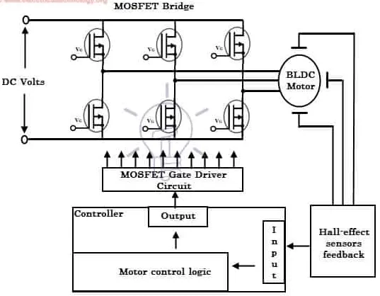
As described above that the electronic controller circuit energizes appropriate motor winding by turning transistor or other solid state switches to rotate the motor continuously. The figure below shows the simple BLDC motor drive circuit which consists of MOSFET bridge (also called as inverter bridge), electronic controller, hall effect sensor and BLDC motor.
Here, Hall-effect sensors are used for position and speed feedback. The electronic controller can be a microcontroller unit or microprocessor or DSP processor or FPGA unit or any other controller. This controller receives these signals, processes them and sends the control signals to the MOSFET driver circuit.
In addition to the switching for a rated speed of the motor, additional electronic circuitry changes the motor speed based on required application. These speed control units are generally implemented with PID controllers to have precise control. It is also possible to produce four-quadrant operation from the motor whilst maintaining good efficiency throughout the speed variations using modern drives
Application of BLDC motor
Brushless DC Motors (BLDC) are used for a wide variety of application requirements such as varying loads, constant loads and positioning applications in the fields of industrial control, automotive, aviation, automation systems, health care equipments, etc. Some specific applications of BLDC motors are
- Computer hard drives and DVD/CD players
- Electric vehicles, hybrid vehicles, and electric bicycles
- Industrial robots, CNC machine tools, and simple belt driven systems
- Washing machines, compressors and dryers
- Fans, pumps and blowers