Week -2
ANS 1: SIMULINK MODEL FOR DOORBELL
Following are the blocks used for doorbell model
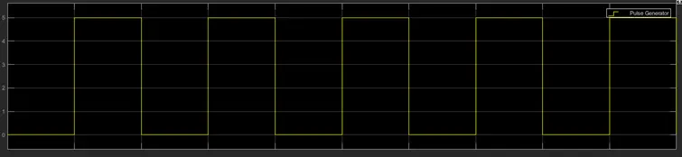
- Pulse generator- It is used to generate the operating signal to ring the bell for 2 sec. Parameters Amplitude- 5, Period- 4 sec, Pulse width- 50%, phase delay- 2 sec are selected.This will give pulse for every 2 sec and off for next 2 sec, this continues till simulation time.
- DC voltage source - It is used to power the coil of solenoid and its voltage is set as per operating voltage of solenoid which is 50V.
- Electrical Reference – It is used to provide electrical reference in the circuit.
- Solenoid – It is used in the circuit as a door bell, its operating voltage is 50V. When a volatge gets applied across solenoid coil, its plunger movement takes place which indicates that bell is ringing.
- Solver configuration – It defines solver settings used for simulatuion.
- Controlled Switch – This switch is controlled by external physical signal provide by pulse generator. Its threshold voltage is set to 3V. Whenever pulse voltage is greater than 3V, this switch become close and remain open otherwise.
- Ideal translational motion sensor – This is used to observed the physical movement of solenoid plunger when solenoid coil energized. Its initial position is set to 0.
- A mechanical translational reference is connected to C port of sensor and solenoid.
- PS-simulink converter & Simulink PS converter – They are used to connect simscape signal to simulink or simulink to simscape vice a versa.
- Scope – It is used to observe generated pulse and position of plunger.
WORKING –
- A pulse signal is created which is on for 2 sec as mentioned in problem. The bell will ring whenever pulse is on i.e for 2 sec.
- A controlled switch is connected in series with battery and solenoid(Bell). This switch gets closed after every 2 sec as per external pulse and the voltage across battery get applied to solenoid coil.
- As soon as voltage applied, plunger movement takes place, which indicates that the bell is ringing, it operates for 2 sec and then off.
- Physical movement of plunger is observed in the scope.
- Simulation time is set to 20 sec.
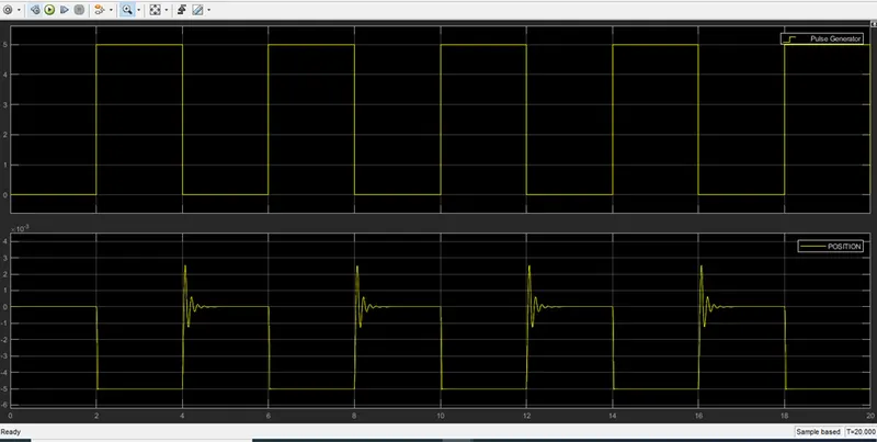
From the above graph it is observed that the pulse is on (giving 5V) between time 2 to 4 sec, 6 to 8 sec and so on and off otherwise (0 V)
When there is no pulse, no plunger movement is observed (0 Position), and when the pulse is on plunger movement is observed( -5mm Position).
The spring constant and damping constant are adjusted to reduce the vibrations.
ANS 2 : SIMULINK MODEL TO SENSE THE TEMPERATURE OF HEATER AND TURN ON & OFF FAN
Following are the blocks used in Simulink model and explanation.
- Controlled temperature source – It maintains positive temperature difference which causes temperature port B greater than port A. Port A is connected to thermal reference. A controlled temperature difference is set by port S which is connected to external signal. This block is used to represent the heater
- Signal builder: It is used to control the temperature of temperature source.
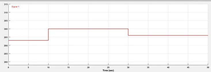
This signal is set so that it generates 293K (20 degree C) between 0 to 20 sec,
300K(27 degree C) between 10 to 30 sec, 296K (23 degree C) between 30 to 50 sec.
- Temperature sensor : It is used to measured the temperature at out port of temperature source.
- Thermistor : NTC type thermistor is used, whose resistance increased as decreased in temperature and viec a versa. The resistance is controlled by external temperature source at port T. It is governed by “R(T) = R0*exp(B*(1/T-1/T0)” equation.
- Resistor R1 : It is connected in series with battery to limit the current. It is linear resistance whose value is set as 2Ω.
- Voltage source 1 : It is used to provide voltage to the circuit and voltage is set as 12V.
- Current sensor : It is used to measure the current in the circuit and is connected to the source.
- Voltage sensor : It is used to measure the voltage across resistor connected in the circuit and is also connected to the scope.
- Voltage controlled switch : As fan has to operate above 25 degree C, so there will be voltage corresponding to 25 degree C across R1 (0.0238 V), voltage greater than or equal to that voltage achieved then switch gets closed and fan will operate. Its threshold is set to 0.0238 V.
- Resistor R2 : It is used to indicate the Fan. Whenever fan has to operate, voltage appear across R2 which is observed by scope named as FAN.
- Voltage source 2 : It is used to power fan circuit and voltage is set to 12 V
Working :
- Signal builder sets the controlled temperature signal (as discussed above) to the S port of Temperature source and B port gives temperature as set by signal builder which indicates the heater.
- The thermistor is connected to the heater and sense the temperature whose resistance value change according to change in temperature of the heater and current value in the circuit also changes accordingly.
- So the voltage drop across resistance R1 also changes as temperature changes.
- Now the fan has to operate above 25 degree C. The voltage across R1 for 25degree C is 0.0238 V which is set as threshold voltrage of voltage controlled switch connected in fan circuit.
- When temperature reaches above 25 degree voltage across R1 become greater than 0.0238 V which is also greater than threshold voltage of switch and switch gets closed and turns ON the fan.
- Here in the fan circuit, fan is indicated by resistor R2. Voltage drop across R2 which is observed by scope indicates that fan is Turned ON.
- Simulation time is set to 50 sec.
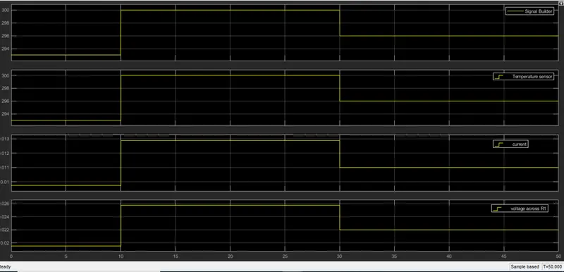
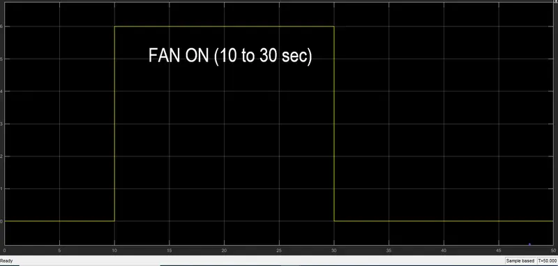
From above graph it is seen that during time 10 to 30 sec voltage of heater increased to 27 degree C which is greater than 25 degree C and voltage appears across R2 indicating Fan turn ON and OFF otherwise.