Week-7 Challenge: DC Motor Control
1. A. Explain a MATLAB demo model named ‘Speed control of a DC motor using BJT H-bridge’.
Solution:
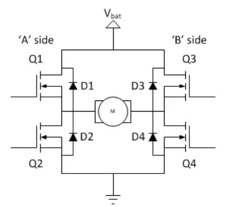
- H-bridge is a simple circuit which helps to control the movement of motor or load in forward or reverse direction. It contains 4 semiconductor switches or a transistors having load at the centre which looks like H structure.
- Q1,Q2,Q3 and Q4 are the switches load is connected in middle, there are 4 diodes connected parallel with each Q switch are known as freewheeling diodes.
- Top and bottom end are connected to the power supply and grounding respectively.
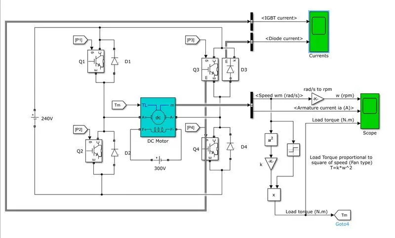
BJT H-bridge model is shown below.
- In this model DC motor is used having specifications as 5HP, 240V, 1750RPM. It is a fan load whose load torque is proportional to square of speed.
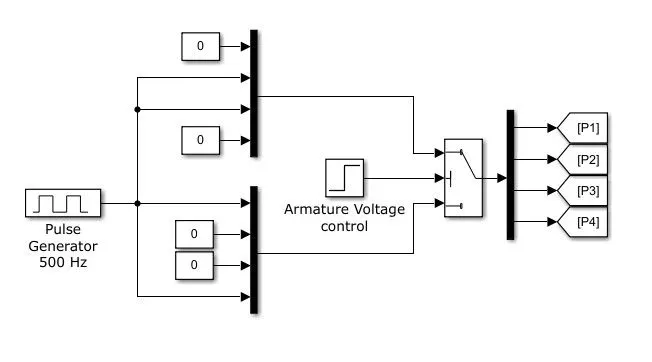
- When Q1 and Q4 gets ON motor rotates in forward direction, where as Q3 and Q2 gets ON motor rotates in reverse direction. A care is taken as no two switches of same side gets ON at same time, it will result into short circuit condition.
- Freewheeling diodes are used especially when the load is inductive in nature as current does not change instantaneously. In reverse polarity of voltage, high current appears at load so these diodes allows such current to pass through it. Such that ripple free current is pssible across load.
- Q1-Q4 is ON motor moves forward direction. When Q1-Q4 is OFF, D2 and D3 operates as Freewheeling diodes.
- Similarly Q2-Q3 is ON motor moves in reverse direction. When Q2-Q3 is OFF, D1 and D4 operates as Freewheeling diodes.
MODEL:
RESULTS:
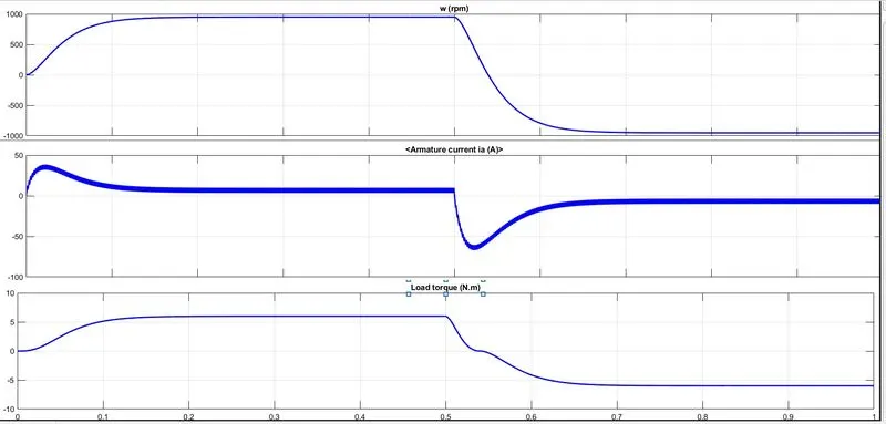
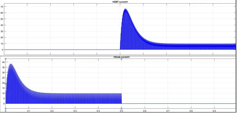
- Above simulation results include speed of motor, armature current and load torque in first graph and Q3 switch current, D3 diode current in second graph.
- While motor running in forward direction Q1 and Q4 are ON and other two IGBT switches are OFF so Q3 is showing in OFF state.
- In forward direction diodes D3 and D2 will also show the response thats why from 0-0.5sec D3 is ON.
B. Comment on the armature current shoot-up from the scope results.
Solution:
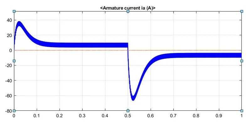
- From above result it is evident current shoot up existed during transition of rotation from positive to negative this is due to transient switching occuring in the circuit.
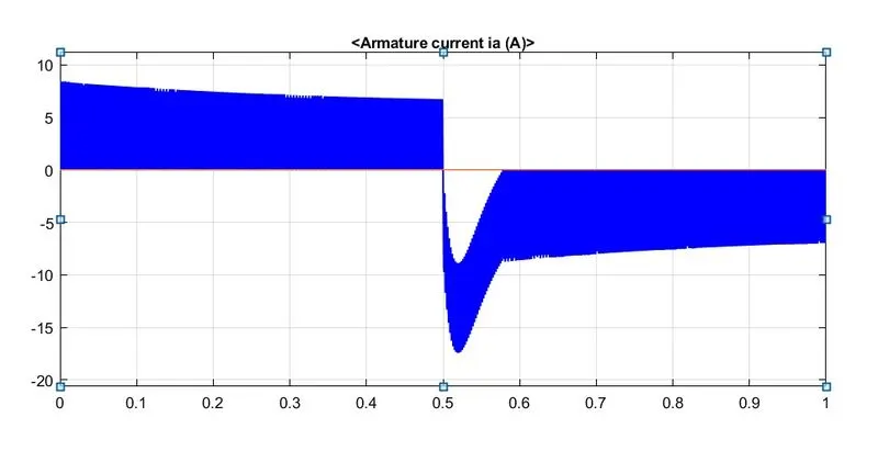
- This surge in the current is reduced by reducing the duty cycle.
- At actual duty cycle was selected as 75% during which surge observed was near to 40 at starting and after 0.5 seconds it was -70 which is in negative direction.
- After changing duty cycle from 75% to 50% surge in current is reduced which is clearly observed in result shown below.
C. Refer to the help section of ‘The Four-Quadrant Chopper DC Drive (DC7) block’. Compare it with the H-bridge model.
Solution:
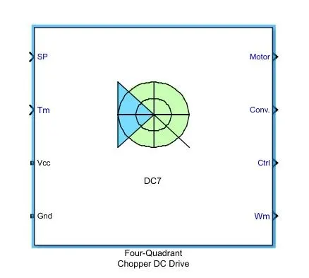
- Below is shown the block of four quadrant chopper DC drive. This drive is used to control speed in four quadrants Q1, Q2, Q3 and Q4.
- Q1: Forward motoring, Q2: Forward braking, Q3: Reverse motoring and Q4: Reverse braking.
- The main advantage of this drive is it uses higher frequency switches which reduces the ripple currents at load side.
- As it uses four switches the complexity of understanding and implementing logic is bit difficult.
- In this circuit armature current oscillations is reduced by smoothing inductsnce connected in series with armature circuit.
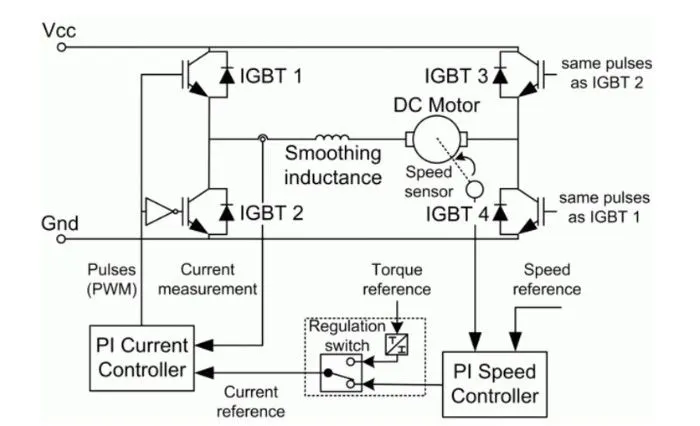
Class E chopper or Four Quadrant chopper:
- Four transistors are connected here along with them four diodes are connected in anti parallel.
- Load as DC motor is connected in between which is shown below.
- During operation of each quadrant which switch will conduct and which will be in OFF state is shown in graph.
- In first and second quadrant this chopper will behave as Step down and Step up chopper respectively.
- In third and fourth quadrant polarity of DC load is reversed.
Comparison of DC7 and H-bridge:
| Sr no. | DC7 | H-bridge |
| 1 |
Operates in 4 stages: Forward motoring, Forward braking, Reverse motoring and Reverse braking. |
Operates in 2 stages: Forward motoring and Reverse motoring. |
| 2 | It has high switching frequency | It has low switching frequency |
| 3 | During transition armature current shows little spike. | During transition armature current shows high spike |
| 4 | Easy to change the direction of motor | To change motor direction current signal has to interrupt |
| 5 | Industrial applications | Robotics applications |
2. Develop a 2-quadrant chopper using simulink & explain the working of the same with the relevant results. (Refer to article - Multiquadrant operation of motor )
Solution:
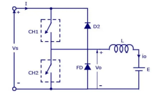
In 2 quadrant chopper two switches CH1, CH2 and two diodes are there FD and D2.
- When CH1 is ON chopper will operate in forward motoring, and current will flow from source to load, in this stage inductor will store energy.
- When CH1 is OFF, FD will be ON and in this stage Vo = Vs which means output voltage equals to source voltage.
- When CH2 is ON chopper will operate in forward braking, in this stage current will flow from load to source hence it will be in negative direction.
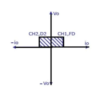
- In two quadrant operation average voltage will always remain positive but average load current may be positive or negative.
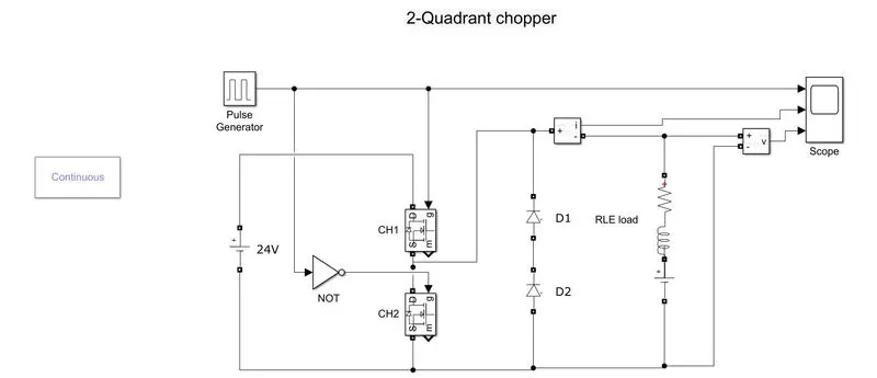
MODEL:
PARAMETERS:
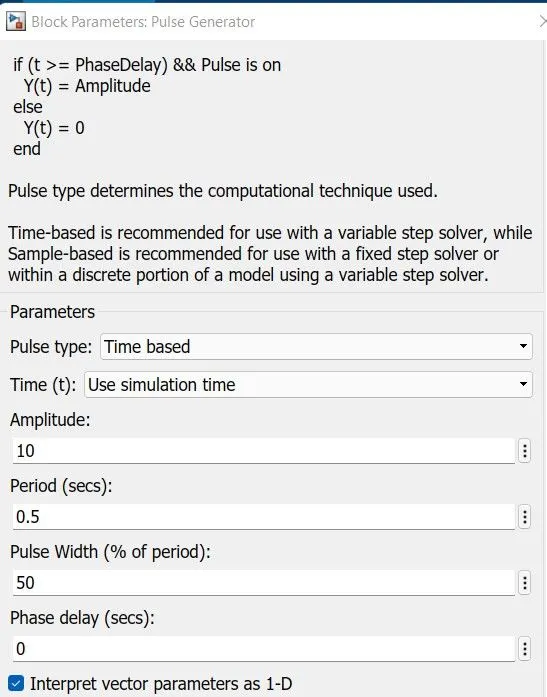
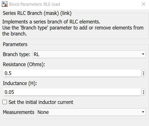
Pulse Generator and Load settings are shown below. To prepare a RLE load series RLC branch is used and for E separate DC voltage source is used of 12V
RESULT:
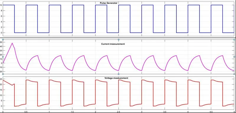
- Current graph is shpwing spike at initial stage which is due to starting troque.
- As discusses earlier average value of voltage is always positive which is shown above. Output voltage is near by 23.7 volts
3. Explain in a brief about operation of BLDC motor.
Solution:
Brushless DC motor
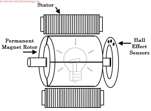
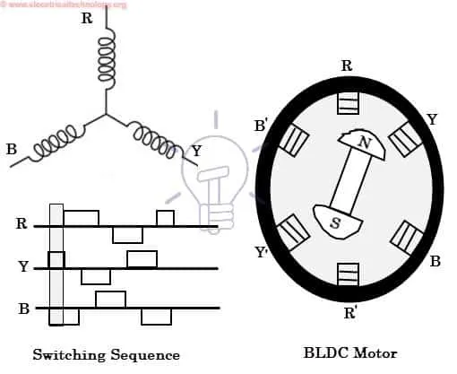
- From a construction and controlling point of view BLDC motors have a permanent magnet in the rotor. This motor is driven by DC supply and instead of using mechanical commutation, electrical commutation is used.
- Commutation is a process in motors which allows switching between phases to energize appropriate windings to help the motor to develop rotating torque.
- BLDC motors are available in single phase and three phase, In three phase BLDC motor permanent magnet rotors are most commonly used.
- The Number of poles in the rotor can vary from 2 to 8 depending upon the application requirement. In order to achieve maximum torque, material with higher flux density is preferred to use.
- These permanent magnet rotates and current carrying conductors are fixed.
- The armature coils are changing its position electronically with the help of Transistors or SCR's in such a way which allows the rotor to rotate in desired direction.
- Hall sensors are set around the stator to sense the position of the rotor and the feedback of these sensors determines the switching of armature current.
- This electronic communication technique in DC motors eliminates the commutator arrangement and brushes which in return also provides more reliable, high speed and less noisy output.
- From an efficiency point BLDC is 10-12% more efficient than brushed DC motors.
- It works on the principle same as conventional DC motors, here the current carrying conductor is stationary and permanent magnet rotates.
- When supply is given to a stator coil it produces a uniform field in the air gap as it behaves as an electromagnet.
- The switching of supply from one to other winding serves the purpose of AC voltage waveform in the DC supply of motor
- Force of interaction between electromagnetic stator and permanent magnet rotor, allows the rotor to rotate.
- BLDC motor is different and superior to brushed motors as it can operate at high speed with great efficiency and better heat dissipation factor.