Week - 4
1. Implement control logic of a “washing machine” using Stateflow as per given sequence:
- If the power supply is available, the system gets activated
- If the Water supply is not available, stop the process & indicate through LED
- Soaking time should be 200s followed by Washing time of 100s.
- Then rinsing happens for next 20s & dryer runs for 50s
Ans.
The chart is shown below of the "washing machine" model, logic is created as per given data.
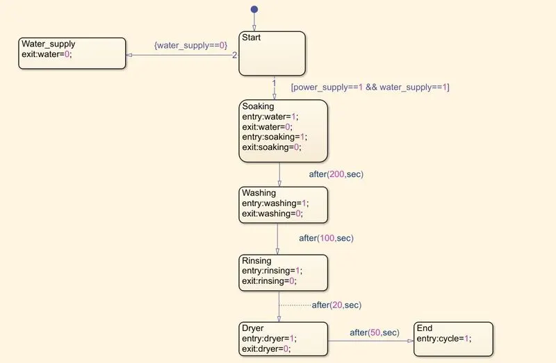
As per question, the cycle initiates for 2 conditions those are:
- Power supply must be ON
- Water supply must be ON
Once the power and water supply is ON the machine perform its activity as per logic developed which includes Soaking, Washing, Rinsing, Drying and then cycle gets finished.
Let's take a look of input and output data of this chart.
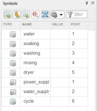
- Here Input datas are shown as: power_supply and water_supply
- Where as Output datas are shown as: water, rinsing, soaking, washing, dryer and cycle.
OUTPUT:
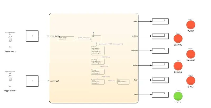
Below is the model containing blocks other than this chart are: Lamp, Display, Toggle switch and Constant blocks
Toggle switch: It toggles between 0 and 1 value to easily differentiate ON and OFF condition of input supply.
OUTPUT: 1
- This is the output of model after running time set as 420 seconds
- Here both toggle switch is in ON condition so the display showing value "1" connected with cycle lamp is in green state, which means cycle is completed.
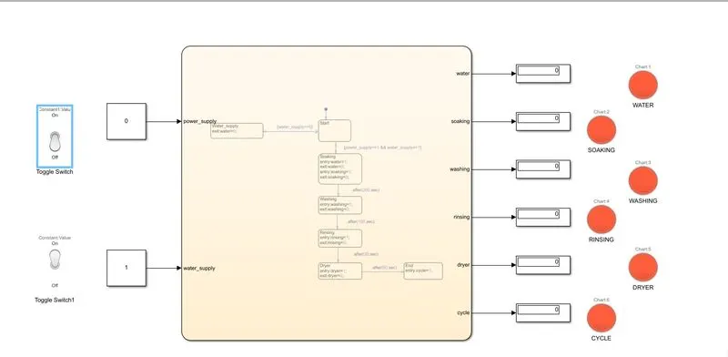
- Let's check the any one of the input switch is OFF
OUTPUT: 2
- Here power supply is OFF so the cycle is not initiated and all the lamps are showing red state with "0" value on display.
JUSTIFICATION:
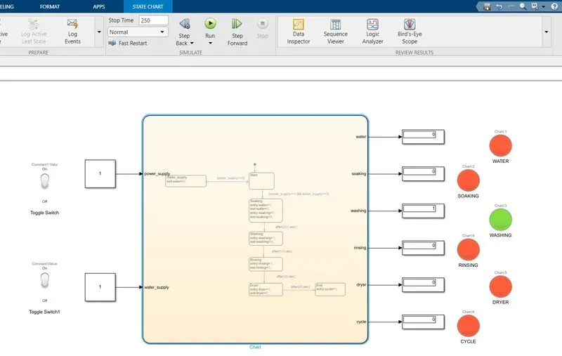
- An random number is selected between 0-420 and simulation is made to ran for 250 seconds as per logic set, washing should be done for 100 seconds, thus simulation time between 200-300 wil show same result.
- Thus display related to washing is showing value "1" and indication of washing is green which means that state is currently running.
2. Make a Simulink chart for the “Gear shift” logic as per below conditions:
Speed Range(kmph) Gear
0 to 15 1
16 to 25 2
26 to 40 3
41 to 60 4
Above 61 5
Ans.
The chart is shown below of the "Gear shift" model, logic is created as per given data.
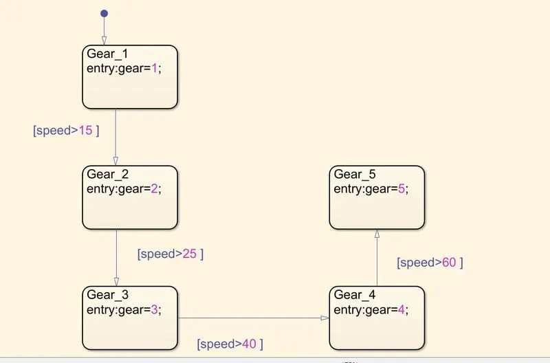
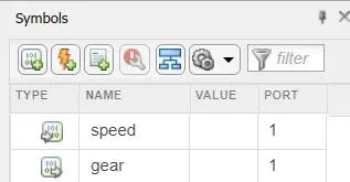
- Here 5 states are shown as per question deamnds, the gear number is changing as per input speed
- Input data is selected as: Speed
- Output data is selected as: Gear
Below is the model file containing other than chart blocks as: Constant, Lamp, Display
- Constant block: It is used to give input speed.
- Lamp: Showing the colour assigned with gear number.
- Display: Showing the gear number.
OUTPUT:
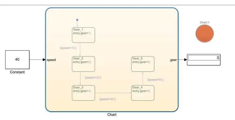
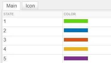
From output we can see when input speed is given as 40km/h using constant block we can check the gear number showing as 3 which is perfect as per logic set and question demands.
JUSTIFICATION:
To justify will check one more output having speed exact at 60Km/h to check whether its showing gear no.4 or not
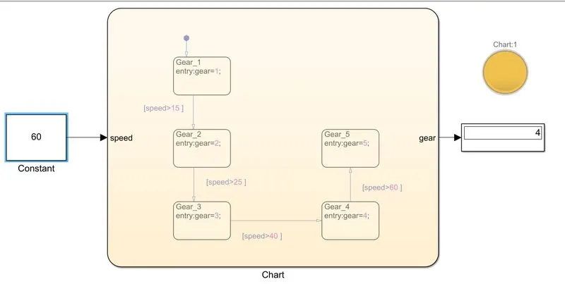
- From above picture we can clearly verify the result.
- Unlike above problem (washing machine ) gear shift chart do not needs exit value to be used as it has only display so changing transition states from one to other is not affected.