Project
Aim: Carry out a system-level simulation of an all-terrain vehicle.
In this project total 6 ATV models are explained which are bit different from each other in respect of functioning related with blocks, although not much different while understanding the working of an individual. The list of following models are mentioned below:
- BAJA ATV model without dashboard.
- BAJA ATV model with engine ratio and rpm
- BAJA ATV model with dashboard.
- BAJA ATV model through data extraction.
- BAJA ATV model mapped lookup table without dashboard.
- BAJA ATV model mapped lookup table with dashboard.
Will see each of these models in detail whatever blocks are used in it, their parameter and results.
- BAJA ATV model without dashboard
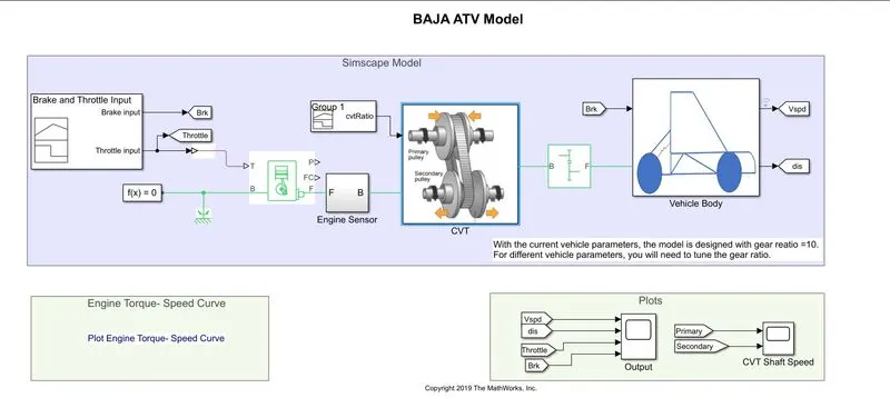
- To understand our first model will first learn about the main blocks used in this model.
- The main blocks are: Generic engine, Vehicle body and CVT.
- Apart from these main blocks various blocks are also used such as Variable ratio gear, Simple gear, double shoe brake, engine sensor, signal builder, tire(magic formula)
Generic engine: This block serves as a source to start any vehicle by providing necessary signals. It has 5 ports which are seen below in picture.
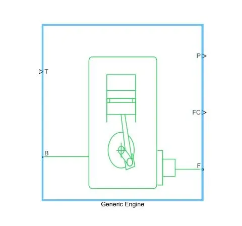
- B: It is connected to rotational motion reference.
- F: It represents the engine crankshaft.
- T: It is a input port where throttle is applied.
- P: It is a output port which represents the engine power.
- FC: It is a output port which repressents the fuel consumption.
Vehicle body: This block represents a vehicle, which can travel only in longitudinal motion parallel to the ground. Various ports used in this block are:
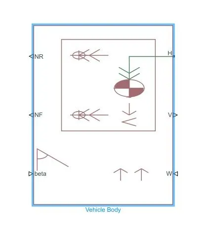
- Beta: It is a input port which represents a inclination angle in radians.
- W: Here the letter W means wind so to create any wind speed effects (in m/s) input signal is provided on this port.
- V: This is the output port represents velocity of the vehicle (in m/s).
- H: Output port represents horizontal movement of tires.
- NR & NF: These two are output ports which represents axle force applied on rear and front tire, which is considered as braking.
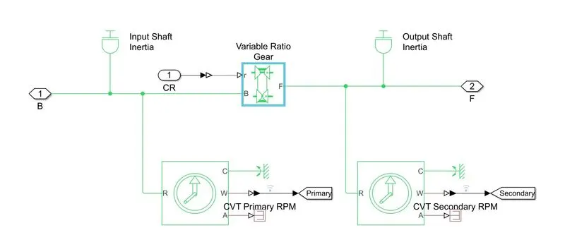
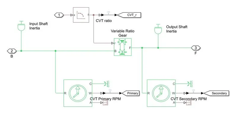
CVT: Continuous variable transmission (CVT) helps to maintain constant angular velocity of a vehicle unlike other transmission systems which has fixed gear ratios and have hard shifts. CVT provides smooth acceleraion and enhanced fuel economy. This block is the subsystem of different blocks which is shown below, It has 2 main blocks those are variable ratio gear and ideal rotational motion sensor.
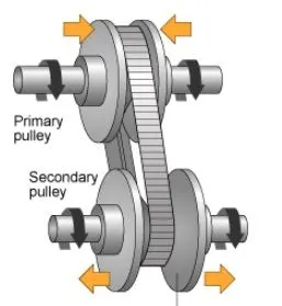
- Variable ratio gear: This block provides CVT to function and provides smooth acceleration to the vehicle by changing gear ratios. The r port in this block is the input signal definig the ratio of input velocity to the output shaft velocity.
- Ideal rotational motion sensor: It senses the RPM of primary and secondary pulley of CVT. Thus it is connected before and after of variable ratio gear to determine the necessary output.
Will understand the working of the simple model now:
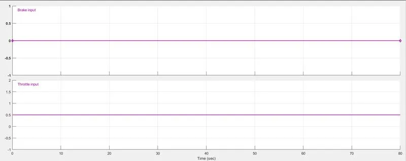
- From signal builder block 2 signals are build, one for throttle value another for break. Below is showing the figure from which we know that this particular model has throttle value set to 0.5 and no brakes are applied on vehicle.
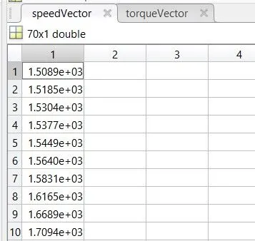
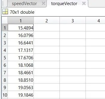
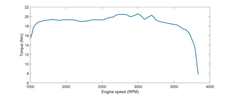
- Speed and torque vector data are introduced in generic engine block from base workspace are shown below:
- Throttle signal is applied to generic engine block, and with the F port of this block is connected to CVT subsystem through engine sensor. Here engine sensor is used to measure the rpm of engine. Below is shown the subsystem of engine sesnor.
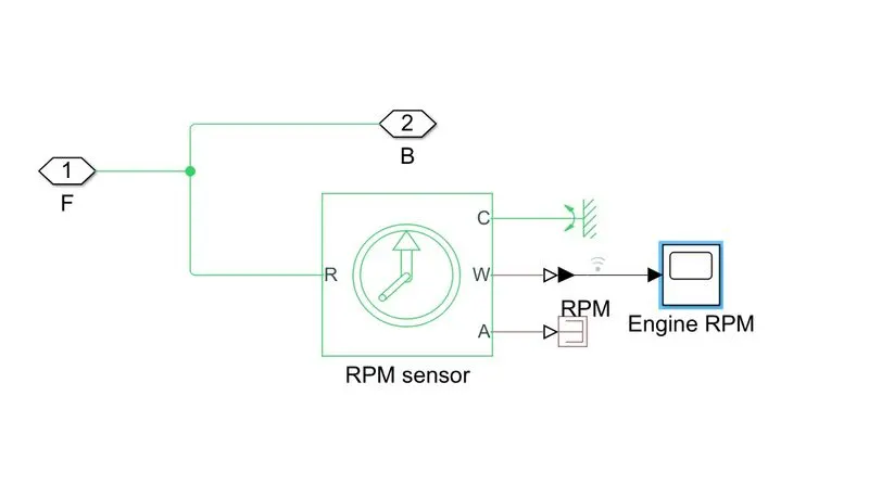
- In CVT subsystem, variable ratio gear is used on which signal is introduced which defines the ratio of input to output shaft velocity. Also 2 sesnors are used to measure the primary and secondary rpm of pulley. Input and output shaft inertia blocks represents as primary and secondary pulley.
- With the help of signal builder block signal is sent to variable gear box.
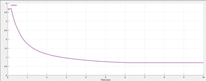
- Simple gear block is used between CVT and vehicle body subsystem, having gear ratio of 10 to reduce or control the speed of vehicle.
- In vehicle body subsystem we see it is a 4 wheel driven system having 2 in front and 2 in rear side.
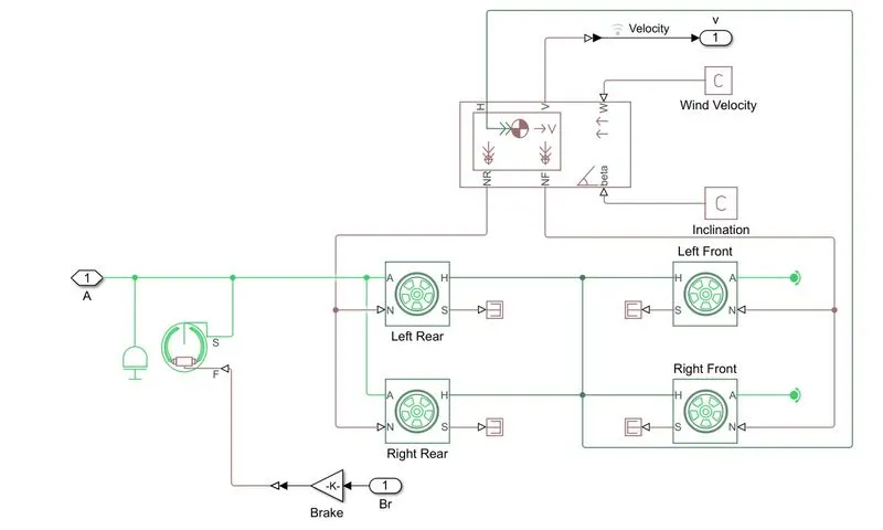
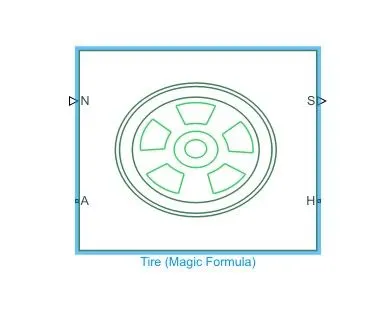
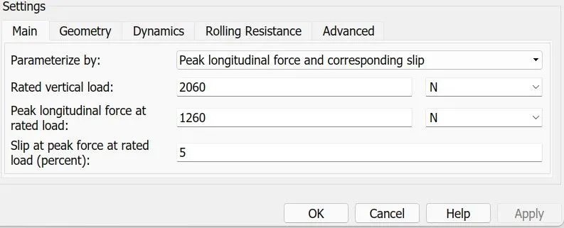
- Out of 4 tires, 2 rear tires are receiving the signal on its A port which suggest that vehicle is rear wheel drive, and all the H ports are connected to the vehicle body those represents the hroizontal motion of vehicle. Here S port which represents the relative slip of tire and road is neglected. All the tires has same parameters with rolling radius of 0.29m. Remaining parameters of tires with its block is shown in below piture.
- Wind and Beta paramters of vehicle body is set to 0 which means no effects of these two quantities are set in this model.
- From tires, N port is connected to NR and NF of vehicle body such that rear and front side of axle forces is made.
- Velocity output is taken on scope using from and goto blocks, where as distance port is integrated first and taken into consideration of main system.
- Below is shown the nature of graph for all the plots in scope.
OUTPUT:
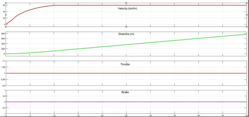
- As vehicle is initially steady as soon as throttle is applied velocity is increasing of vehicle. As no brakes are applied here there's no spikes observed in the graph.
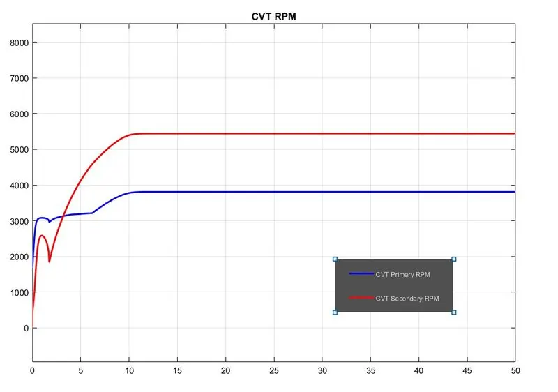
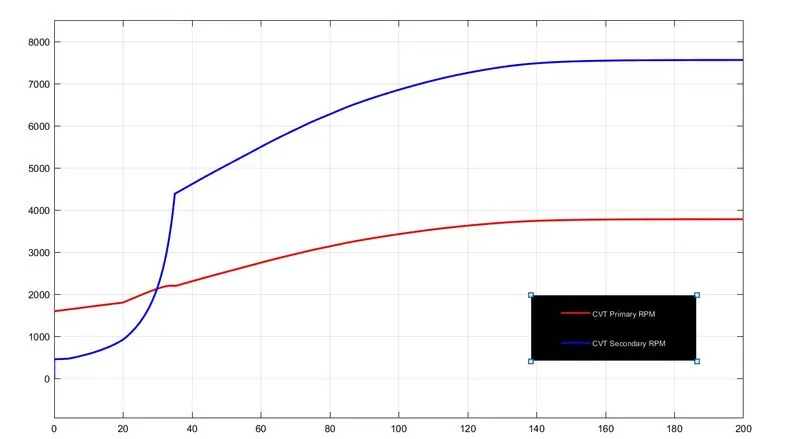
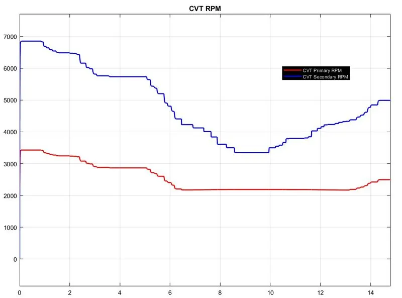
- For more understanding simulation is made to run for 50secs to view the nature of CVT primary and secondary graph. We can observe initial small jerk on CVT primary while starting.
CVT Primary and Secondary RPM:
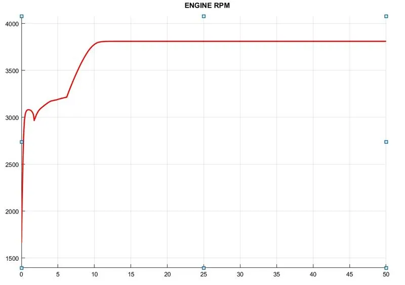
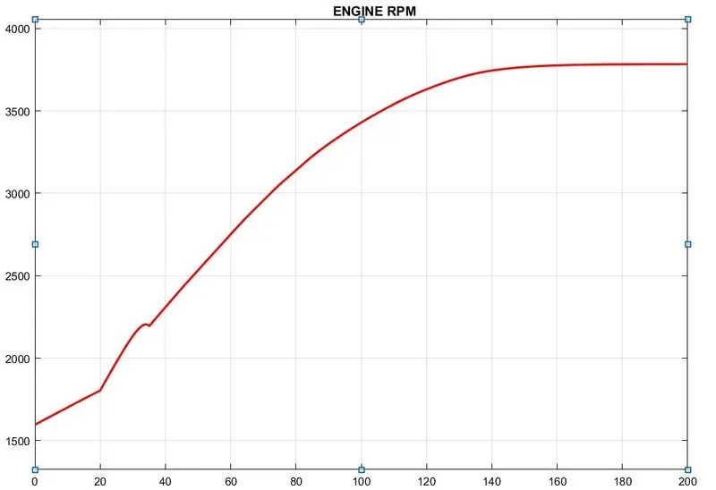
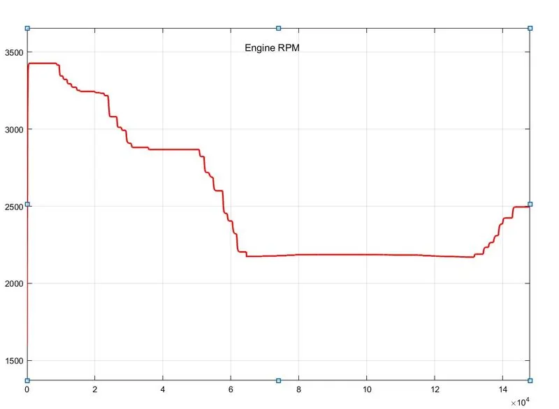
Engine RPM:
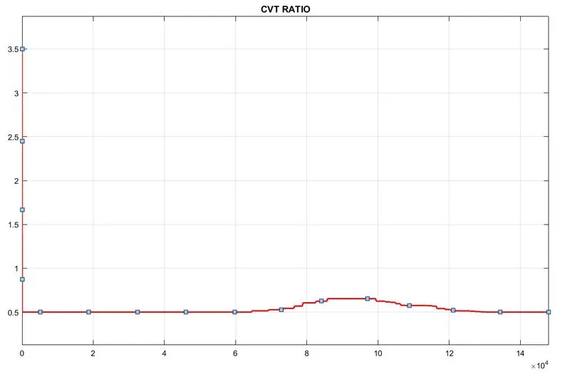
Initially as throttle is set to 1, and then as CVT ratio is decreased we can observe in period of 0-5seconds engine RPM is also increasing and as CVT ratio is constant after that engine is constant nearby 3800RPM.
2. BAJA ATV model with engine ratio and rpm
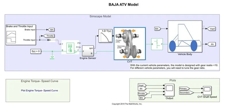
- This mode is same as previous one, but instead of signal builder block for CVT; 1-D lookup table is loaded in base workspace which shows the same resuts so not discussing again
- Below images are shown of scope results after running simulation for 50seconds.
3. BAJA ATV model with dashboard.
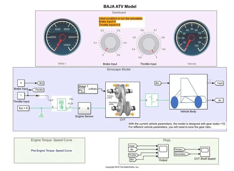
- This model is same as previous one, only a dashboard is equipped additionally for user through which throttle and brake inputs are applied. This eradicates the use of signal builder block for it.
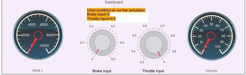
- Below is shown 2 images of before and after use of throttle and brakes. Initially throttle was set to 1 and no brakes were applied and then inputs are changed by varying knobs and outputs are captured and shown below to understand its result.
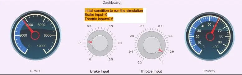
OUTPUT:
- Initially throttle was set to 1 so the velocity of vehicle was 60Km/h. After 2secs brakes are applied and also throttle is brought to 0.7 so velocity has decreased.
- Similarly for remaining time we can compare both input and output signals to undertand the nature of scope and observe the changes.
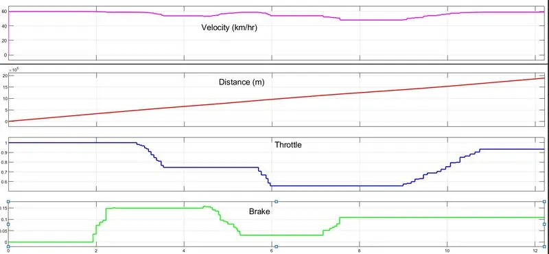
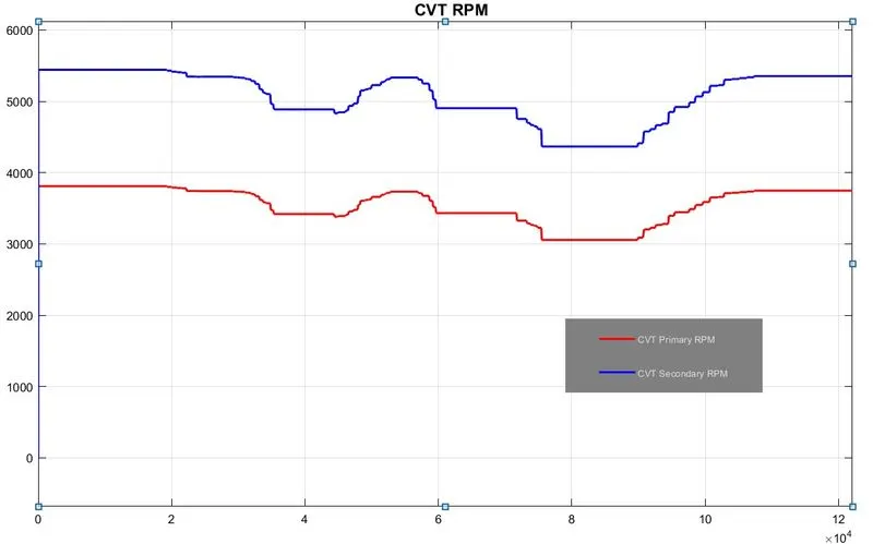
CVT Primary and Secondary RPM and ENGINE RPM:
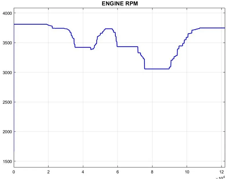
Effects of input signals and CVT ratio can be seen in CVT and Engine RPM as well, which we can notice while comparing as this is already discussed for very first model, so will not get into much detail about it.
4. BAJA ATV model through data extraction.
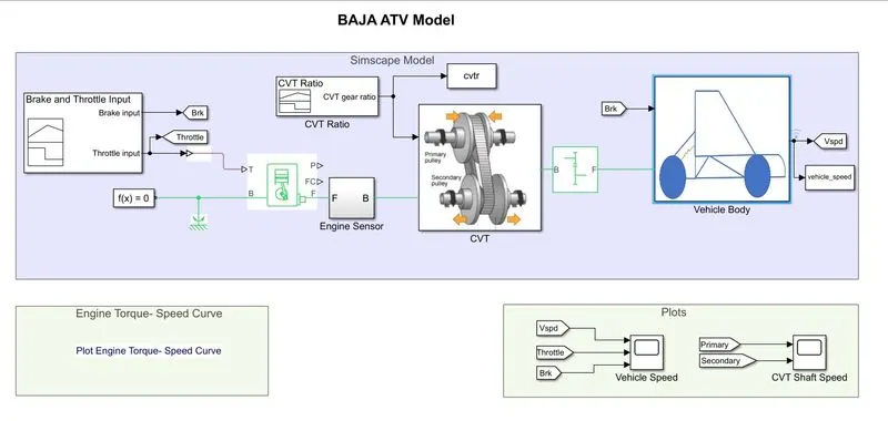
- This model is same as first model, only one minor change is observe physically that is 'To Workspace' block is used to extract value of CVT ratio and vehicle speed.
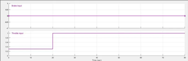
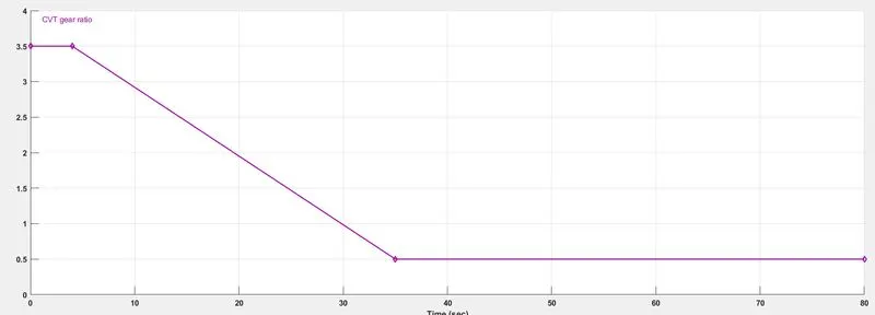
- Apart from physical observation, in this model signal used for throttle and CVT inputs are different which is shown below.
- Also here gear ratio in simple gear block is 12
INPUT:
- From input signals we can observe throttle is 0.3 initially upto 20 seconds and then instantaneously it jumped to 1.
- No brakes are applied as its constant at 0 value.
- CVT ratio is 3.5 upto 5 seconds and then it started decreasing till 35th seconds and reach to 0.5 value which remains constant.
OUTPUT:
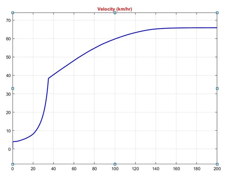
- For better understanding input signals of throttle and brake are not combined with output signal of velocity from scope.
- Velocity is instantaneously increased at 20th second as throttle is set to 1 from 0 with a variable CVT ratio.
- As we can observe at 35th second CVT ratio is constant to value 0.5 so that velocity is also tried to become steady above speed of 60.
CVT Primary and Secondary RPM:
5. BAJA ATV model mapped lookup table without dashboard.
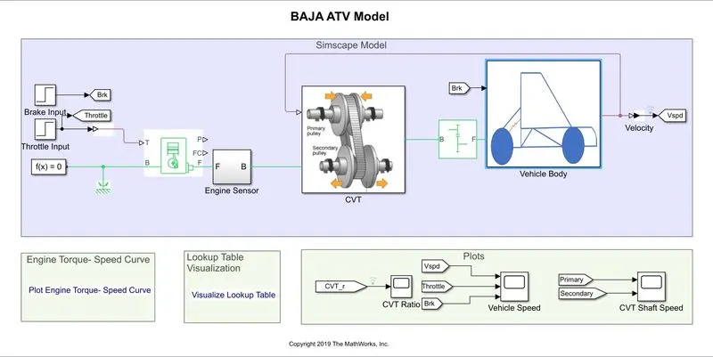
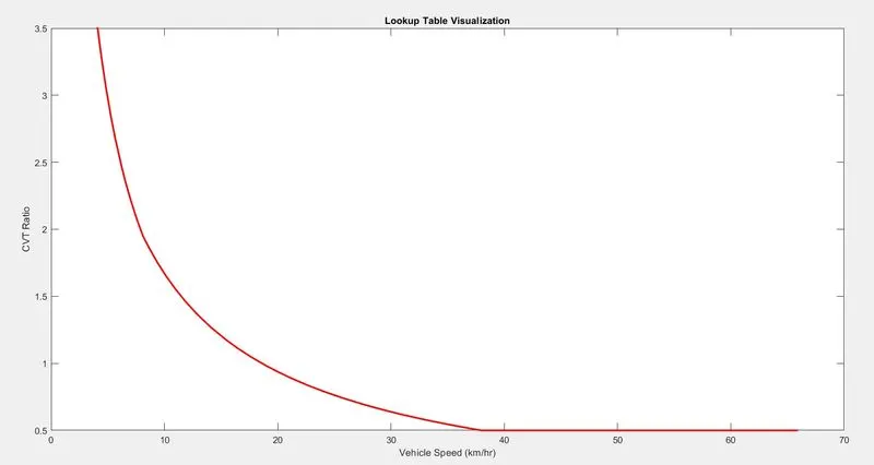
- This model has same work flow having bit changes in implemeting. From physical observation a closed loop system is created in which a feedback path is build from output velocity of vehicle is send to input signal of variable gear ratio with the help of lookup table block.
- Below a picture is shown of CVT subsystem and lookup table chart which values are provided into the transmission system based on that feedback process vehicle changes the gear and brings out more smooth experience to the driver.
- Besides these feedback system, here for input signals instead of signal builder step signal block is used whose throttle and brake signals are same as previous one.
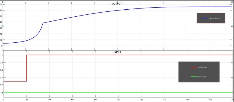
- Throttle signal: step time=20sec, initial value=0.3, final value=1
- Brake signal: step time=35sec, initial value=0, final value=1
- CVT ratio is also same as previous one.
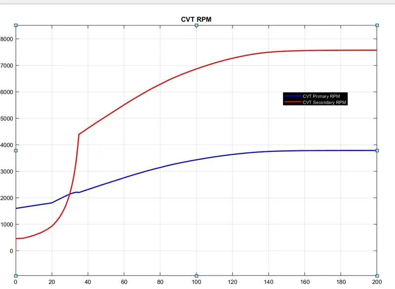
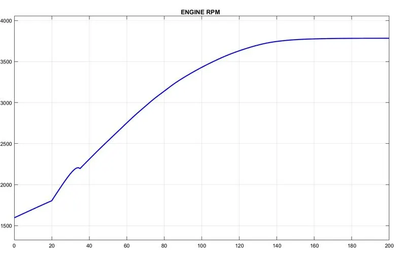
- As workflow is same after running simulation for 200seconds we get the following results from scope which are identical.
6. BAJA ATV model mapped lookup table with dashboard.
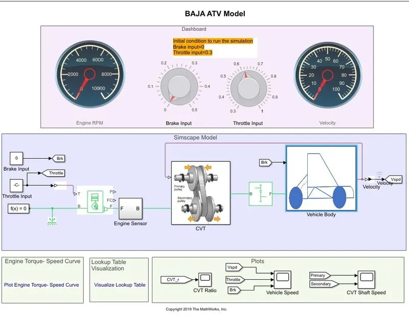
- As discussed before dashboard provides user to change input signal using knobs for that. This whole model is same as previous one so will not discuss about feedback process again instead of that will change the inputs using knob and compare the results of outputs.
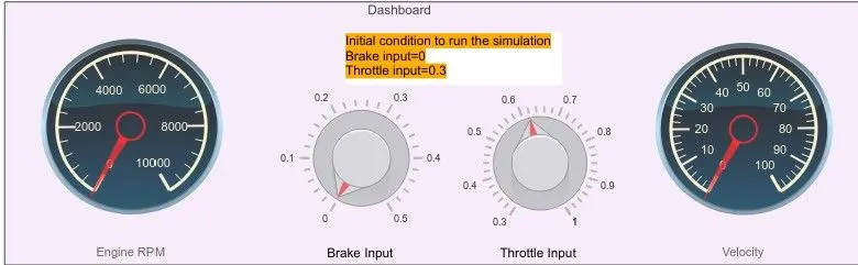
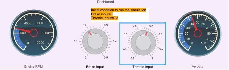
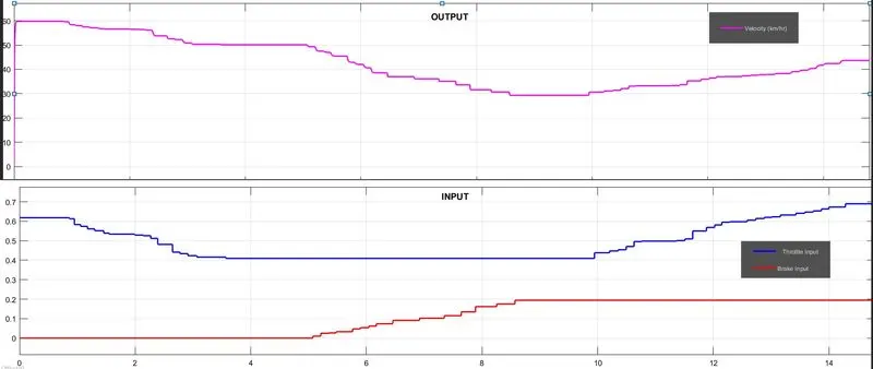
- Initially throttle was set to near by 0.6 and no brakes were applied. As a user input is changed using knobs and throttle is first decreased and then increased to 0.7 where as brakes were brought up from 0 to 0.2.
OUTPUT:
- Initially for few seconds throttle was near to 0.6 so the output of vehicle showing constant velocity at 60Km/h and then as throttle is decreased velocity also decreased. Below shown result of scope is clearly tells about the effect of output as input is given by user.
OBSERVATIONS:
- Total 6 models were observed in this practical having bit differences in each of it but workflow is same.
- Talking about parameters we can notice for first three models gear ratio is set to 10, while for remaining three it was 12.
- Generic engine block and Tire block parameters are not changed for any model.
- Three different ways are used for input signals, such as using signal builder block, step block and using knobs.
- CVT ratio extraction done by three different ways such as signal builder block, using lookup table and using lookup table from closed loop system.