Week-7 Challenge: DC Motor Control
#1.
A. Speed control of a DC motor using BJT H-bridge
Simulink Model
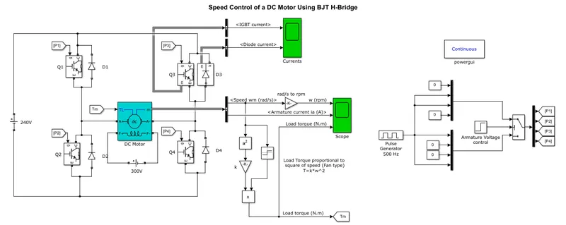
- The Bipolar Junction Transistor (BJT) when used for power switching applications, operates as an IGBT. When it is conducting, a forward voltage Vf is developed between collector and emitter. So the IGBT block can be used to model the BJT device.
- The DC motor uses the preset model (5 HP 24V 1750 rpm). The armature voltage can be varied from 0 to 240 V when the duty cycle is varied from 0 to 100%.
- The H-bridge consists of four BJT/Diode pairs. Two transistors are switched simultaneously: Q1 and Q4 or Q2 and Q3.
- When Q1 and Q4 are fired, a positive voltage is applied to the motor and diodes D2-D3 operate as free-wheeling diodes when Q1 and Q4 are switched off. In this state the motor moves in foward direction.
- When Q2 and Q3 are fired, a negative voltage is applied to the motor and diodes D1-D4 operate as free-wheeling diodes when Q2 and Q3 are switched off. In this state the motor moves in reverse direction.
- When Q1 and Q4 are fired,the motor starts to rotate in the forward didrection with a duty cycle of 75%. At 0.5 sec Q2 and Q3 are fired and the armature voltage is reversed and which will lead the motor to rotate in the backward direction.
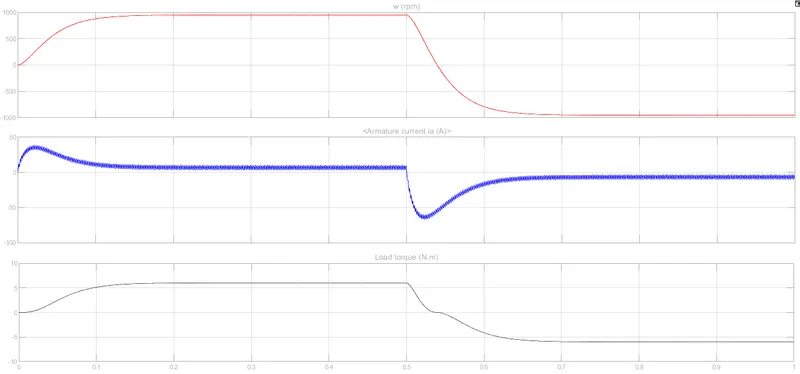
The graph shows Speed, Armature current and torque when Q1 and Q4 for 0 - 0.5 sec and Q2 and Q3 for 0.5 - 1 Sec.
B. Armature Current Shoot-up
The initial armature current shoot up is due to the sudden increase in voltage regulated by the 75% duty cycle.
- 240*75% = 180V
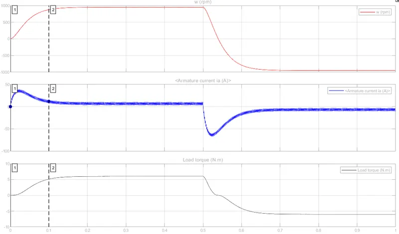
- At starting point their is a armature current shoot up.
- As the speed increses the armature current is positive for 0.5 Sec.
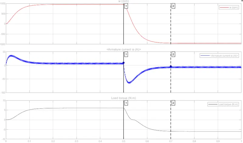
- After 0.5 Sec the rotation of the motor is reversed and the armature current is dropped down instantsty and thearamature curent is negative.
- As the motor chages its direction their is shoot up in the armature current due to the reversal of armature voltage.
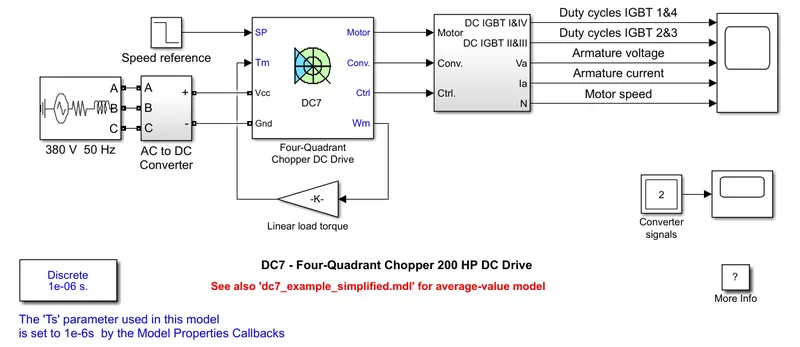
C. The Four-Quadrant Chopper DC Drive (DC7) block
Working
The initial bus voltage is set as 515 V via the GUI block.
Start the simulation. You can observe the motor armature voltage and current, the four IGBT pulses and the motor speed on the scope.
The mechanical torque of the load is proportional to the speed due to the motor is coupled to a linear load.
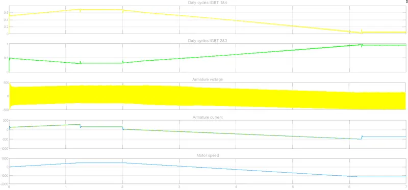
The speed reference is set at 500 rpm at t = 0 s. Observe that the motor speed follows the reference ramp accurately (+400 rpm/s) and reaches steady state around t = 1.3 s.
At t = 2 s, speed reference drops to -1184 rpm. The current reference decreases to reduce the electromagnetic torque and causes the motor to decelerate with the help of the load torque.
At t = 2.2 s, the current reverses in order to produce a braking electromagnetic torque (dynamic braking mode). This causes the DC bus voltage to increase.
At t = 3.25 s, the motor reaches 0 rpm and the load torque reverses and becomes negative. The negative current now produces an accelerating electromagnetic torque to allow the motor to follow the negative speed ramp (-400 rpm/s). At t = 6.3 s, the speed reaches -1184 rpm and stabilizes around its reference.
Comparison between the Four-Quadrant Chopper DC Drive model and H-bridge model
| Four-Quadrant Chopper DC Drive | H-bridge model |
|
- Can be operate in 4 different modes:
- Regenerative Braking is Possible. - PI regulators are used to control armature current and speed. - Used to interupt one signal to control another signal. - Controlling is easy and efficiency. |
- Can only operate in 2 modes:
- Regenerative braking is not possible. - No controllers are used. - Switches the polarity of the applied voltage. - Low efficiency. |
#3. BLDC Motor
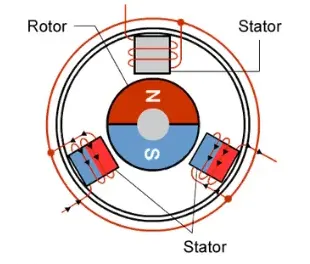
- A Brushless DC motor is a permanant magnet synchronous electric motor which is driven by DC power.
- In BLDC motor the rotor is a permanent magnet and the windings are provided in the stator with acts as an electromagnet. Since the windings are not moving the no need for a brush and a commutator.
- The rotation of the rotor in BLDC motor is achived by changing the direction of the magnectic field generated by the rotor surrounding stationary coils. To control the speed the magnitude and direction of the current into the coils is adjusted.
- The BLDC operation depents on the position of the rotor magnetic field which is sensed by hall sensor. By the posotion of the rotor the coils are powered accordinly.
Advantages of BLDC Motor
- Mechanical energy losses due to friction is less beacuse of the absence of brushes.
- Can be opearted in high speed conditions.
- There is no spark from the commutators.
- Electromagnetic interferance is low.
- Speed conrol of BLDC motor is easy.
- Low noise
- Less maintanance.
Disadvantages of Motor
- Cost of manufacturing is high.
- The limited high power could be supplied to BLDC motor, otherwise, too much heat weakens the magnets and the insulation of winding may get damaged.