Project 2 Adaptive Cruise Control
Adaptive Cruise Control
Aim
Develop an Adaptive Cruise Control Model in MATLAB Simulink as per the Requirement Document given.
After the development of the Simulink Model the following process are carried out:
- Requirement Tagging & Traceability
- SLDD creation
- Configuration Parameter changes
- Model Advisor check
- Code Generation
Steps and Parameters Included in Developing the ACC Model
General Settings for Code Generation
Storage class for Input signals: ImportedExtern
Storage class for Output signal: Export to File
Storage class for local signals: localizable
Storage class for calibration signals: Const.
Choose sample time for all signals as 0.01s
The Adaptive Cruise Control Model is developed on the input genarted by Camera Image Capture technology and Radar technology.
Step in Development of Adaptive Cruise Control Model
As per the given requirements there are 3 Main Requirements
Requirement 1 – Lead Vehicle
A subsystem is created named ‘Lead Vehicle’
Inside the subsystem two input:
- 'CameraInput_LeadVehicle'
- 'RadarInput_LeadVehicle'
Both the input signals are added using an Add block a resolved output signal is generated named: 'LeadVehicle_Speed'.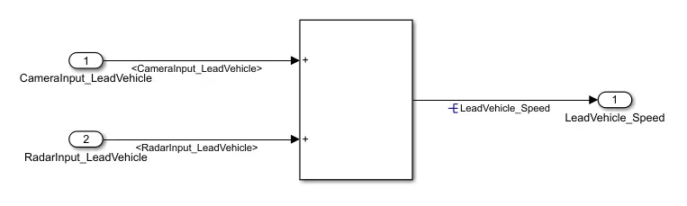
Fig 1: Inside Lead Vehicle Subsystem
Requirement 2 – Drive Vehicle
A subsystem is created named ‘Drive Vehicle’
Inside the subsystem there is 3 input signal in which 2 signals are propated and 1 signal is resolved from Adaptive Cruise Control Algorithm:
- ‘CameraInput_DriveVehicle’
- ‘RadarInput_DriveVehicle’
- ‘Acceleration_Mode’ (Resolved Signal from Adaptive Cruise Control Algorithm)
The summation of 3 input signals generated a resolved signal named: 'DriveVehicle_Speed'
The Radar input signal : ‘RadarInput_DriveVehicle’ signal is resolved to generate a signal named 'LeadVehicle_Detected'.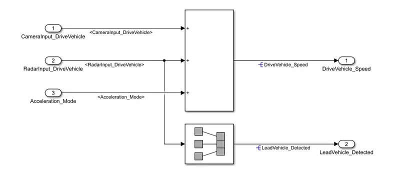
Fig 2: Inside Drive Vehicle Subsystem
Requirement 3 – Adaptive Cruise Control Algorithm:
A subsystem named ‘Adaptive_Cruise_Control_Algorithm’ is created.
The subsystem has 8 input signals to state machine system:
- 'Time_Gap'
- 'Set_Speed'
- 'Set_Gap'
- 'CruiseSwitch'
- 'SetSwitch'
- 'LeadVehicle_Speed' (Fed by Lead Vehicle Subsystem Output - Requirement 1)
- 'DriveVehicle_Speed' (Fed by Drive Vehicle Subsystem Output - Requirement 2)
- 'LeadVehicle_Detected' (Fed by Drive Vehicle Subsystem Output - Requirement 2)
The above 8 signals are fed to a State Machine System named 'Adaptive_Cruise_Control_Logic' to generate an output signal named ‘Acceleration_Mode’ which governs the vehicle speed with respect the requirements and inputs of the camera and radar.
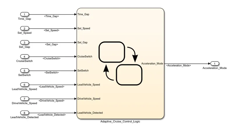
Fig 3: Inside Adaptive_Cruise_Control_Algorithm Subsystem
Adaptive_Cruise_Control_Logic
'Adaptive_Cruise_Control_Logic' is the State Machine System which has the logical explanation of the Adaptive Cruise Control Model with governs the speed and mode of acceleration of the vehicle.
The State Machine System consist of 3 Mode of Opeation:
- OFF Mode
- STANDBY Mode
- ON Mode
Development of State Machine System 'Adaptive_Cruise_Control_Logic'
The Sate Machine has 3 states named:
ACC OFF MODE
Acceleration_Mode = 0 is set as entry condition.
The ACC OFF MODE State is governed by input signal CruiseSwitch:
If CruiseSwitch == 1, state ACC STANDBY MODE will get activated.
If CruiseSwitch == 0, state ACC OFF MODE will get activated either from ACC ON MODE or ACC STANDBY MODE.
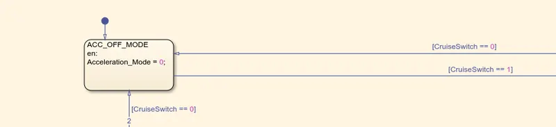 Fig 4: ACC_OFF_MODE
ACC STANDBY MODE
Acceleration_Mode = 1 is set as entry condition.
ACC STANDBY MODE is governed by both input signals CruiseSwitch & SetSwitch.
If CruiseSwitch == 1, state ACC STANDBY MODE will get activated.
If CruiseSwitch == 0, state ACC OFF mode will get activated either from ACC ON MODE or ACC STANDBY MODE.
If SetSwitch == 1, state ACC ON MODE will get activated.
If SetSwitch == 0, state ACC STANDBY MODE will get activated.
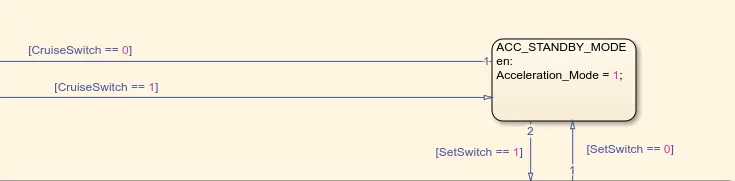 Fig 4 : ACC_STANDBY_MODE
ACC ON MODE
ACC ON MODE has 6 other Sub-States namely:
- LeadVehicle_Detected_Follow
- LeadVehicle_Not_Detected
- LeadVehicle_Detected_Resume
- LeadVehicle_Not_Detected_Resume
- LeadVehicle_Speed_lessthan_Set_Speed
- LeadVehicle_Speed_equal_Set_Speed
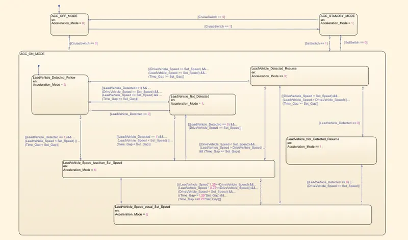
Fig 6: ACC_ON_MODE with 6 Sub- States
Development of 6 Sub-States of ACC ON MODE
- LeadVehicle_Detected_Follow
Acceleration_Mode = 2 is set as entry condition.
Condition - [LeadVehicle_Detected == 0], transit to LeadVehicle_Not_Detected.
Condition - [(LeadVehicle_Detected == 1) && (LeadVehicle_Speed < Set_Speed) || (Time_Gap < Set_Gap)], transit to LeadVehicle_Speed_lessthan_Set_Speed.
- LeadVehicle_Not_Detected
Acceleration_Mode = 1 is set as entry condition.
Condition - [(LeadVehicle_Detected==1) && (DriveVehicle_Speed == Set_Speed) && (LeadVehicle_Speed >= Set_Speed) && (Time_Gap >= Set_Gap)], transit to LeadVehicle_Detected_Follow.
Condition - [(LeadVehicle_Detected == 1) && (LeadVehicle_Speed < Set_Speed) || (Time_Gap < Set_Gap)], transit to LeadVehicle_Speed_lessthan_Set_Speed.
- LeadVehicle_Detected_Resume
Acceleration_Mode =3 is set as entry condition.
Condition - [(DriveVehicle_Speed == Set_Speed) && (LeadVehicle_Speed >= Set_Speed) && (Time_Gap >= Set_Gap)],transit to LeadVehicle_Detected_Follow
Condition - [LeadVehicle_Detected==0], transit to LeadVehicle_Not_Detected_Resume.
Condition - [(DriveVehicle_Speed < Set_Speed) && (LeadVehicle_Speed > DriveVehicle_Speed) && (Time_Gap >= Set_Gap)], transit to LeadVehicle_Speed_equal_Set_Speed.
- LeadVehicle_Not_Detected_Resume
Acceleration_Mode = 1 is set as entry condition.
- LeadVehicle_Speed_lessthan_Set_Speed
Acceleration_Mode = 4 is set as entry condition.
Condition - [(LeadVehicle_Detected == 0) && (DriveVehicle_Speed == Set_Speed)], transit to LeadVehicle_Not_Detected.
Condition - [((LeadVehicle_Speed*1.25>=DriveVehicle_Speed) && (LeadVehicle_Speed * 0.75<=DriveVehicle_Speed)) && (DriveVehicle_Speed < Set_Speed) && ((Time_Gap<=1.25*Set_Gap) && (Time_Gap >=0.75*Set_Gap))], transit to LeadVehicle_Speed_equal_Set_Speed.
- LeadVehicle_Speed_equal_Set_Speed
Conditions - [(LeadVehicle_Detected == 0) || (DriveVehicle_Speed <= Set_Speed)], transit to LeadVehicle_Not_Detected_Resume.
Conditions - [(DriveVehicle_Speed < Set_Speed) && (LeadVehicle_Speed > DriveVehicle_Speed) || (Time_Gap >= Set_Gap)], transit to LeadVehicle_Detected_Resume.
Conditions - [(LeadVehicle_Speed<Set_Speed) && (LeadVehicle_Speed<DriveVehicle_Speed) || (Time_Gap == 0.75*Set_Gap)], transit to LeadVehicle_Speed_lessthan_Set_Speed.
ADAPTIVE CRUISE CONTROL SYSTEM
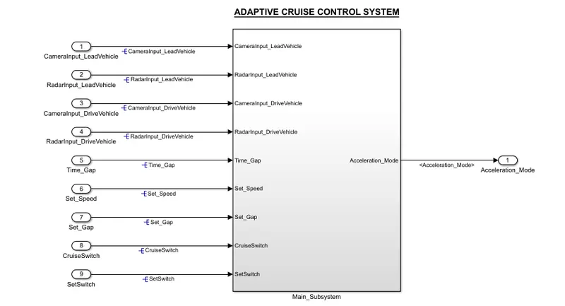
Fig 7 : The Main Sub System of Final ADAPTIVE CRUISE CONTROL SYSTEM
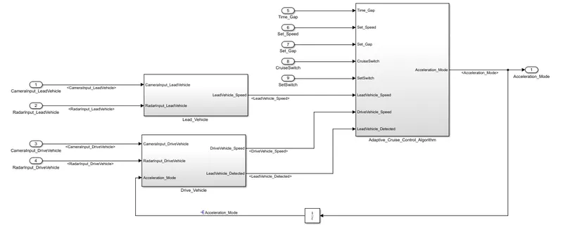
Fig 8 : Screenshot containing the 3 Main Requirement Subsystem
Requirement Tagging & Traceability
- Create a word document containing the requirements 1, requirement 2 and requirement 3.
- Select the Requirement 1 in word (High light).
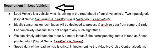
Fig 9: Requirement Highlighting
- In MATLAB select Requirement 1 subsystem ' Lead_Vehicle' --> Right Click --> Requirements --> Link to selection in work.
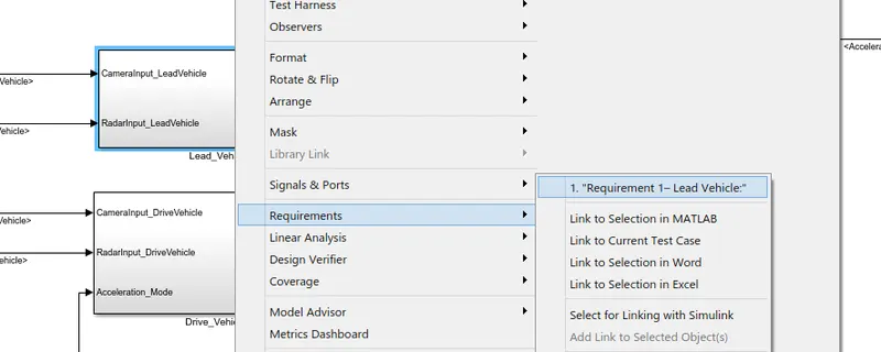
Fig 10 : Requirement Tagging of Lead_Vehicle Subsystem
- Repeat the above step same for other 2 subsystem 'Drive_Vehicle' and 'Adaptive_Cruise_Control_Algorithm'.
SLDD Creation
- In the ACC Simulink model go to Modelling --> Model Setting --> Model Properties --> External Data --> New --> Assign name (ACC_DD.sldd) for the data dictionary.
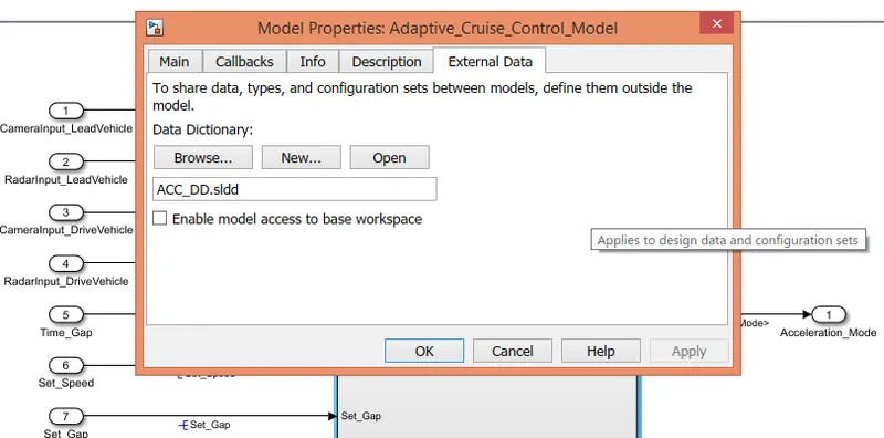
Fig 11 : Creation of Data Dictionary File
- As per requirements and the given Signals & Calibration Data List the Data Dictionary has been created.
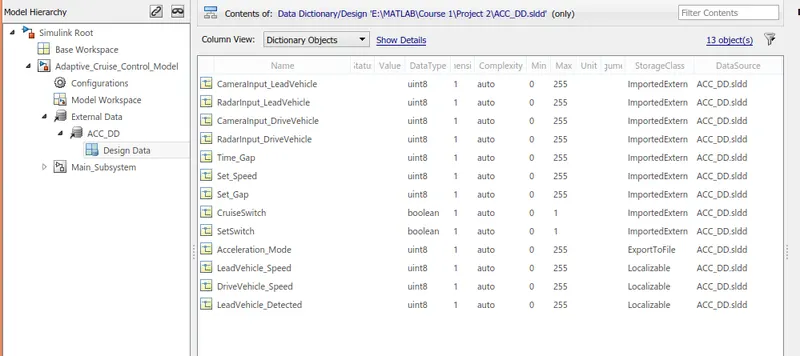
Fig 12 : Simulink Data Dictionary for ACC
Configuration Parameter
- For Code Generation the Configurations Parameters are changed as per requirement.
- In Simulink Model : Model Setting --> Code Generation --> Set System Target file as 'ert.tlc' and languate as C as we are using Emedded Coder for Code Generation.
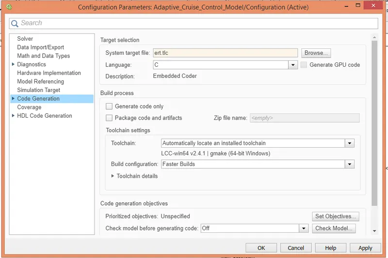
Fig 13 : Setting up Configuration Parameters
Model Advisor check
- Model Advisor Test has een Run to Check for any errors.
- To Run Model Advisor Check : Modelling --> Model Advisor --> Choose the System Hirarchy --> Run
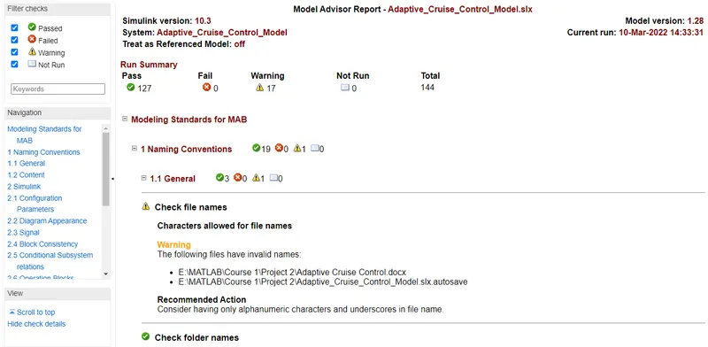
Fig 14 : Model Advisor Check Report
CODE GENERATION
- For Code Generation : Option APPS --> Embedded Coder --> Generate Code --> Build --> Generate Code
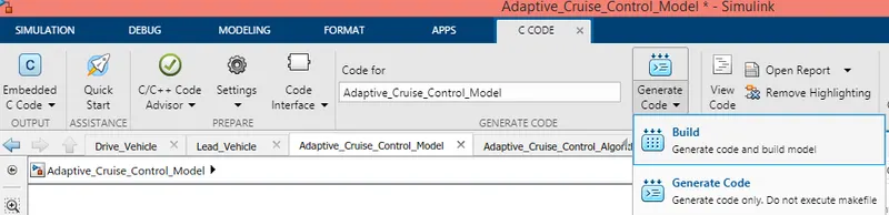
Fig 14 : Steps for Code Generation
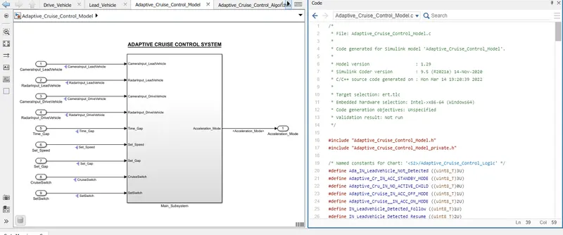
Fig 16 : Code Generation has been done succesfully
RESULT
As per the requirements the simulink model has been succesfully created and code has been generated.
This sumulink model is capable of Adaptive Cruise Control Feature for passenger cars allows the host vehicle to adapt to the speed in line with the flow of traffic with the help of Radar and Camera systems.
The followings files are being attached :
- Simulink Model
- Data Dictionary
- Model Advisor Report
- Code
- Requirements