Week - 4
#1 Implement control logic of a “washing machine” using Stateflow as per given sequence
Aim
To implement a control logic of a washing machine using stateflow as per the following given sequence.
- If the power supply is available, the system gets activated.
- If the Water supply is not available, stop the process & indicate through LED.
- Soaking time should be 200s followed by Washing time of 100s.
- Then rinsing happens for next 20s & dryer runs for 50s.
Procedure
- Creating a stateflow logic for washing machine using simulink with given informations.
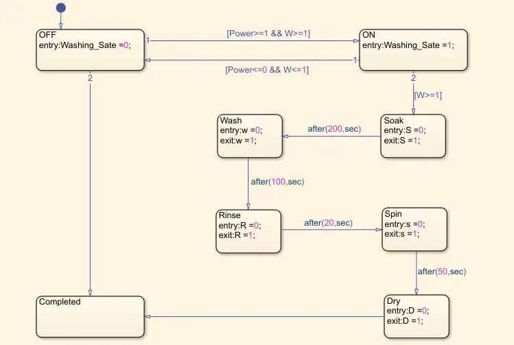
Fig 1: Stateflow Logic of the system
Steps in creating the ststeflow logic
- A Chart is Created.
- Inisde the chart, different states of the systems are created as shown in the aove figure.
- The entry and exit conditions has been assigned as per given details.
- The delay of each state is initialised.
- Input and Output of the stateflow has been set.
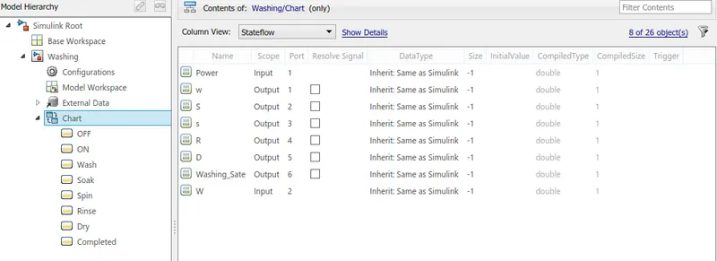
Fig 2: Input and Outputs in Model Explorer
- The simulink Model has been created.
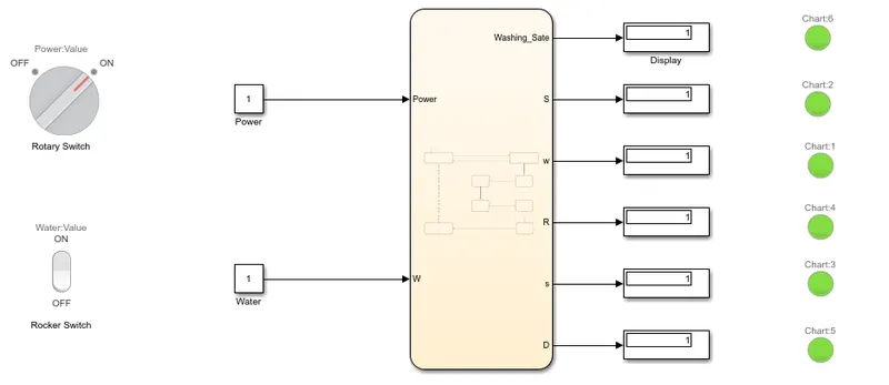
Fig 3: Simulink Model of the Washing Machine Syatem
Steps in designing the simulink model
- Input to the stateflow chart is provided with Costant Blocks.
- A Rotary Swich and Rocket Switch is used to Toggle ON and OFF Power and Water respectively.
- Status of each state outputs are displayed using Display Blocks.
- A Lamp is provided to visually analyse eash state.
Result
Each state output are given below y changing the run time.
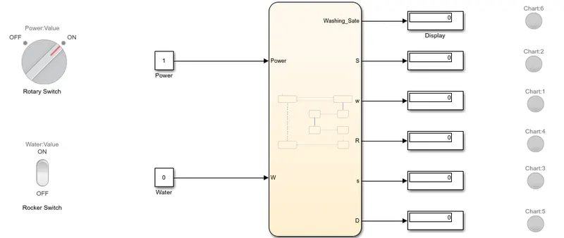
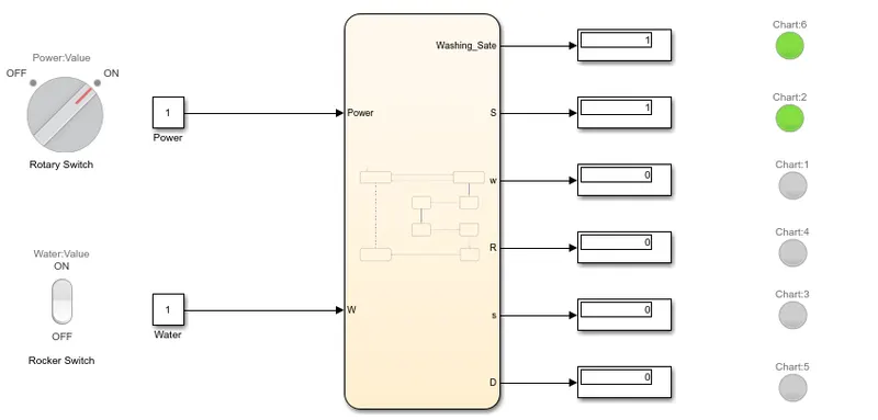
Fig 4.1 : Power ON & Water OFF Fig 4.2 : Power ON & Water ON
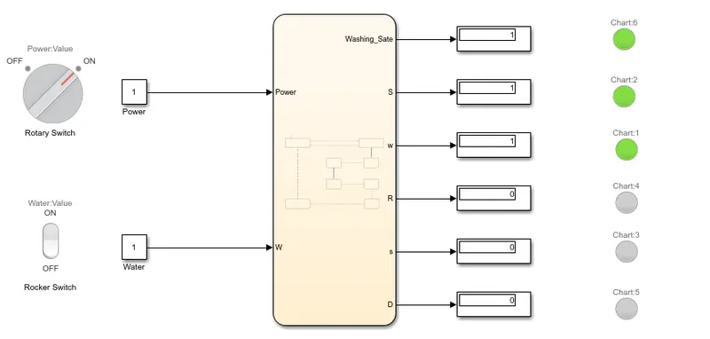
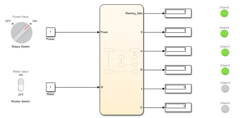
Fig 4.3 : After 200 Sec Soaking Fig 4.4 : After 100 Sec Washiing
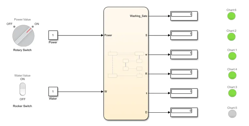
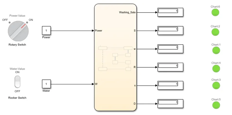
Fig 4.4 : After 20 Sec Rinsing Fig 4.6 : After 50 Sec Drying
After the process all the LED Lamps are in ON State.
#2 Design a imulink chart for the “Gear shift” logic
Aim
To make a Simulink chart for the “Gear shift” logic as per below conditions:
Speed Range(kmph) Gear
0 to 15 1
16 to 25 2
26 to 40 3
41 to 60 4
Above 61 5
Procedure
- The stateflow model has been disgned.
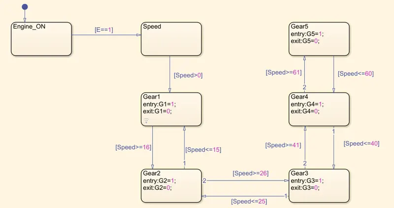
Fig 1: Stateflow Logic of the Gear System
Steps in creating the ststeflow logic
- A Chart is Created.
- Inisde the chart, different states of the systems are created as shown in the above figure.
- The entry and exit conditions has been assigned as per given details.
- The speed range of each gear has been setup for each gear(State).
- The simulink Model has been created.
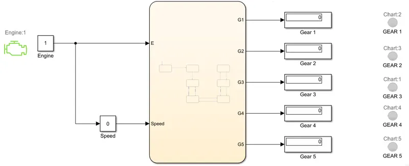
Fig 2: Simulink model of Automatic Gear System w.r.t Speed
Steps in designing the simulink model
- Engine ON Input to the stateflow chart is provided with Costant Blocks.
- After Engine is ON the speed input is fed with the help of Slider Gain Block.
- Status of each state outputs (Gear) are displayed using Display Blocks.
- A Lamp is provided to visually analyse which gear is currently in use.
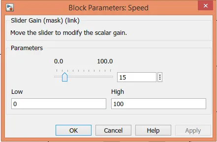 Fig 3: Slider gain to adjust the speed input
Result
Each Gear is used with respect the speed input.
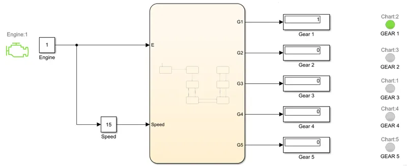
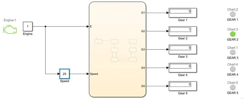
Fig 4.1: Gear = 1 Fig 4.2: Gear = 2
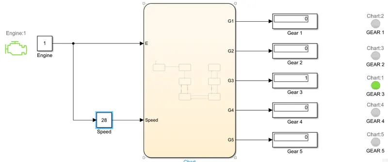
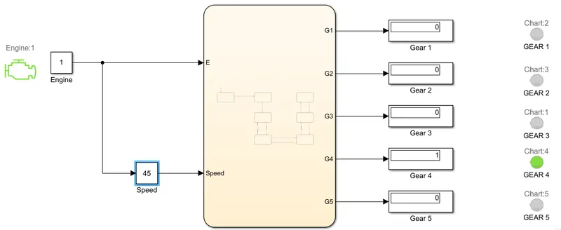
Fig 4.3: Gear = 3 Fig 4.4: Gear = 4
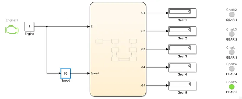
Fig 4.5 : Gear = 5
Speed has been changed & Gear is Displayed.