Project 1 (Mini Project on Vehicle Direction Detection
Vehicle Direction Determination
Objective
Development of MATLAB Simulink model by Identify the direction of vehicle for creating Autonomous driving system & Advanced Driver Assistance Features using Camera input and steering wheel input.
Development of Simulink Model
The requirements has been given for the development of the Simulink model.
- As per requirements the primary input signals are:
- Steering wheel input as yaw rate (Signal name: SteeringWheel_YawDegreeInput)
- Camera input (Signal Name: CameraInput_RoadSign)
- Steering wheel input values are compared against:
- Right Turn Input values (Right_Turn_AngularLimit)
- Left Turn Input values (Left_Turn_AngularLimit)
- Straight Forward Input values (Straight_Drive_Steering_Angle)
By comparing the above 3 input values with the given calibration data in the question generates an output signal which recognise the current steering position (Vehicle_Turn_Status).
- Camera input signals are compared against:
- Right signal sign as input (RightTurn_RoadSign)
- Left signal sign as input (LeftTurn_RoadSign)
- Straight signal sign as input (Straight_RoadSign)
By recognizing the road signal sign with the camera Vehicle_Direction_Indicator signal is generated.
Steps to develop Simulink Model
- A Primary subsystem is created with 2 input signals
- SteeringWheel_YawDegreeInput
- CameraInput_RoadSign
- Output of the subsystem is Vehicle_Direction_Indicator
- Each originating input signals are being resolved.
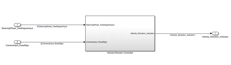
Fig 1: 'Vehicle Direction Controller' Subsytem
- In the Vehicle Direction Controller subsystem there is two other subsystems which contain the logical model as per given Requirement-1 and Requirement-2.
- The Requirement - 1 is fed by the input signal - SteeringWheel_YawDegreeInput and output signal - Vehicle_Turn_Status is generated.
- The Requirement - 2 is fed by the input signals - CameraInput_RoadSign and the Requirement-1 output - Vehicle_Turn_Status and output signal - Vehicle_Direction_Indicator is generated.

Fig 2: 'Requirement 1 & Requirement 2' Subsystem
Requirement 1 Logic
- The Steering wheel input signal - SteeringWheel_YawDegreeInput is compared against 3 angular values using a Relational Operator ‘==’ block.
- Right Turn Input values - Right_Turn_AngularLimit
- Left Turn Input values - Left_Turn_AngularLimit
- Straight Forward Input values - Straight_Drive_Steering_Angle
- The 3 angular values are fed in the data dictionary as per given values in the Signals & Calibration Data List.
- The 3 compared output is fed to 3 switches to generate a output signal -Vehicle_Turn_Status.
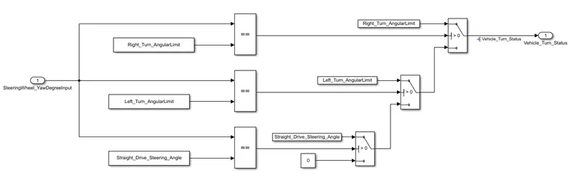
Fig 3: 'Requirement 1' Logical System
Requirement 2 Logic
- The output fed by requirement 1 subsystem - Vehicle_Turn_Status is compared against calibration values using a Relational Operator ‘==’ block.
Right signal sign - (RightTurn_RoadSign)
Left signal sign - (LeftTurn_RoadSign)
Straight signal sign - (Straight_RoadSign)
- The 3 Boolean value obtained from relational operator is fed to Logical operator ‘AND’ to compare against the Boolean values obtained from the camera - CameraInput_RoadSign
- The signals hence generated is combined with the help of a us Creator to generate signal - Vehicle_Direction_Indicator
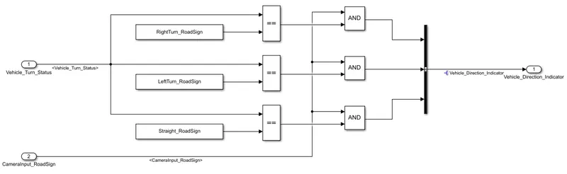
Fig 4: 'Requirement 2' Logical System
Requirement Tagging of Simulink Model
- Create a word document containing the requirements 1 and requirement 2.
- Select the Requirement 1 in word (High light).
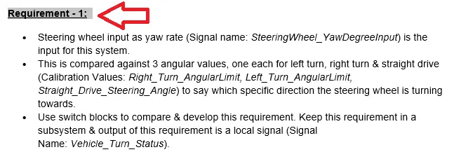
Fig 5: 'Requirement 1' in word high lightened
- In MATLAB select Requirement 1 subsystem --> Right Click --> Requirements --> Link to selection in work.
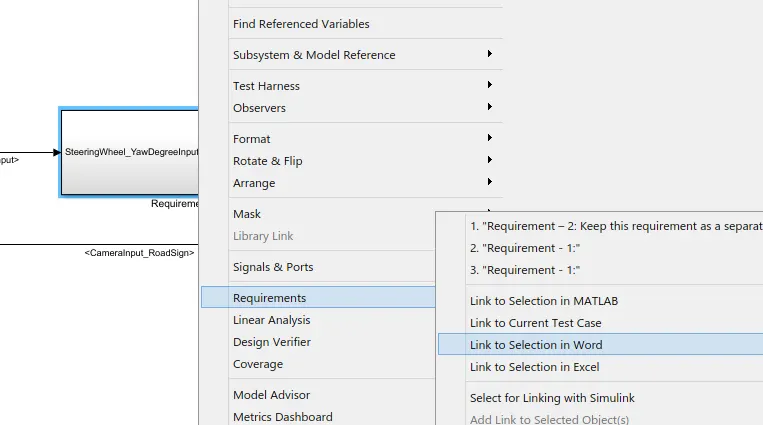
Fig 6: Steps for requirement tagging
- Repeat the above step same for the Requirement 2 Subsystem.
Creation of Simulink Data Dictionary file (SLDD)
- In the Simulink model go to Modelling --> Model Setting --> Model Properties --> External Data --> New --> Assign name for the data dictionary.
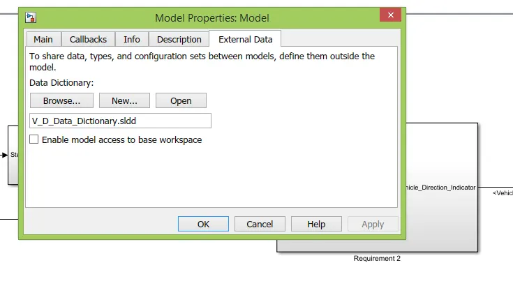
Fig 7: Creation of Data Dictionary
Simulink Data Dictionary data
- As given in the question the Signal and Calibration data list are added in to the data dictionary.
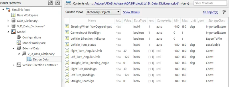
Fig 8: Simulink Data Dictionary
Check Modelling Standard for MAB
- To check whether the created model meets the Modelling standard of MAB a Model Advisor test is being carried out.
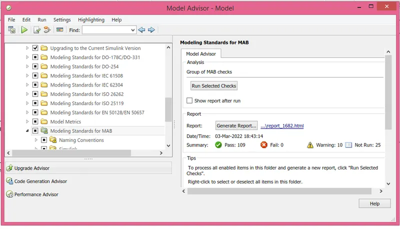
Fig 9: Model Advisor showing MAB Standard Completion
Model In Loop Test Harness
- Select main Subsystem --> Right Click --> Test Harness --> Create for Vehicle Direction Controller.
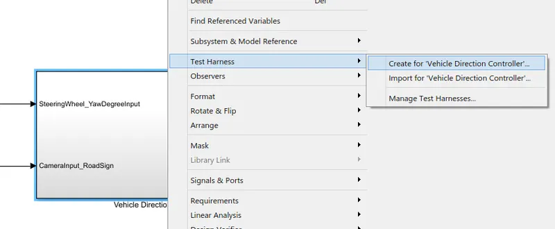
Fig 10:Steps for Test Harness
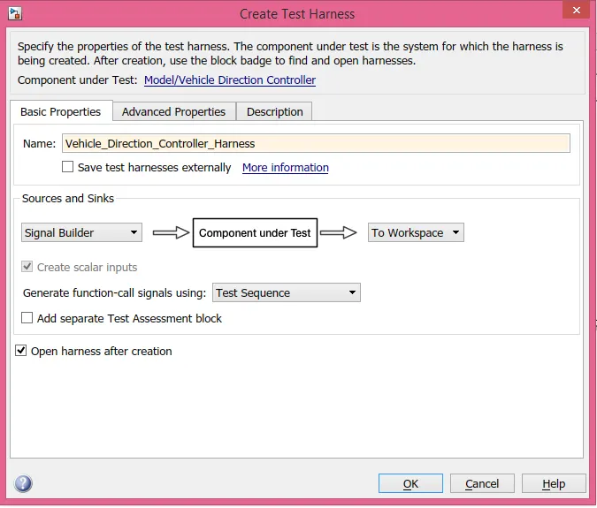
Fig 11: Creation of MIL Test Harness
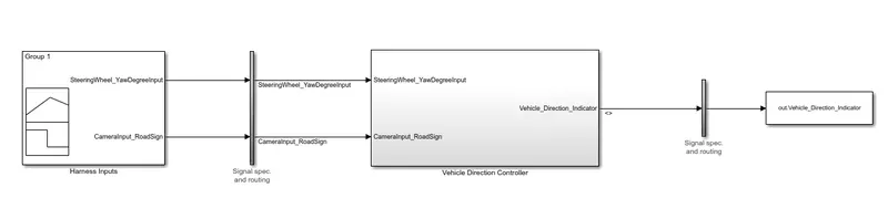
Fig 12: MIL Template for Vehicle Direction Controller
- Test Cases are uploaded using excel to obtain the graph.
Software In Loop
- Select the main system --> Right click --> C/C++ code --> Generate S- Funtion
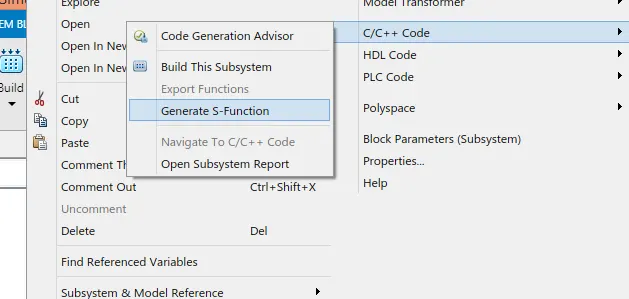
Fig 13: SIL Cretation