Project
BAJA All-Terrain Vehicle (ATV)
Aim
To study and prepare a detailed report on system-level simulation of an all-terrain vehicle.
Objective
Study about all-terrain vehicle on a system level stimulation on Simulink and prepare a technical report with the features and properties of the vehicle.
Introduction to All-Terrain Vehicle
An All-Terrain Vehicle (ATV) is a specially designed motor vehicle, which can be, used in different road conditions like Off-road, Mountain, Highways etc. This type of vehicle uses four low-pressure or non-pneumatic tires. The seats is designed in a way that the driver can sit and stand while driving and handlebars for steering control for fast and accurate controlling of the vehicle.
BAJA All-Terrain Vehicle with CVT
Continuously Variable Transmission (CVT) is a type of automatic transmission, which produces more power to wheel ratio, and a smooth transmission on drive than the traditional automatic transmission vehicle. The main difference between the traditional and CVT transmission system is that the CVT systems does not have any gear ratios in fixed steps
A CVT can change seamlessly through a continuous range of gear ratios. This helps to control the engine to operate at a constant RPM while the vehicle moves at varying speeds.
The BAJA CVT uses two pulleys connected by a belt or chain.
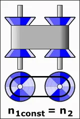
Fig 1: Basic Model of CVT
Working of CVT
The CVT have variable-diameter pulleys. A belt rides between the two cones. V-belts get their name from the fact that the belts bear a V-shaped cross section, which increases the frictional grip of the belt.
When the two cones of the pulley are far apart, the belt rides lower and the radius of the belt loop going around the pulley gets smaller.
When the cones are close together, the belt rides higher and the radius of the belt loop going around the pulley gets larger.
Simulink Model of the BAJA ATV Model with CVT
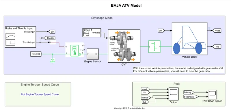
Fig 2: Simulink Model of BAJA ATV Model with CVT System
The major blocks used in building the system are:
- Signal Builder Block – To provide Brakes and Throttle Input
- Generic Engine - System-level model of spark-ignition and diesel engines suitable.
- Ideal Rotational Motion Sensor - This block measures angular velocity or angle in a mechanical rotational network.
- Variable Gear Ratio Block - Represents a variable ratio gearbox such as implemented by mechanical belt CVT, electric, or hydraulic transmissions.
- Simple Gear - Represents a fixed-ratio gear or gearbox.
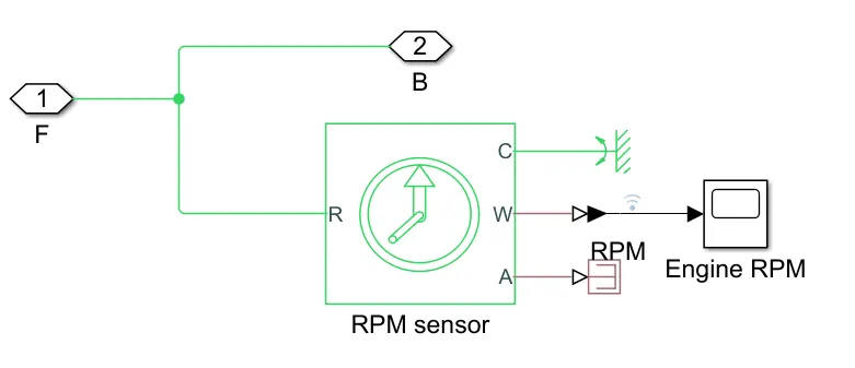
Fig 3: Engine Sensor Subsystem
Simulink CVT Model
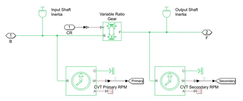
Fig 4: Subsystem of CVT model
In the above CVT model, two Ideal Rotational Motion Sensors are set as Primary and Secondary RPM or Pulley of CVT.
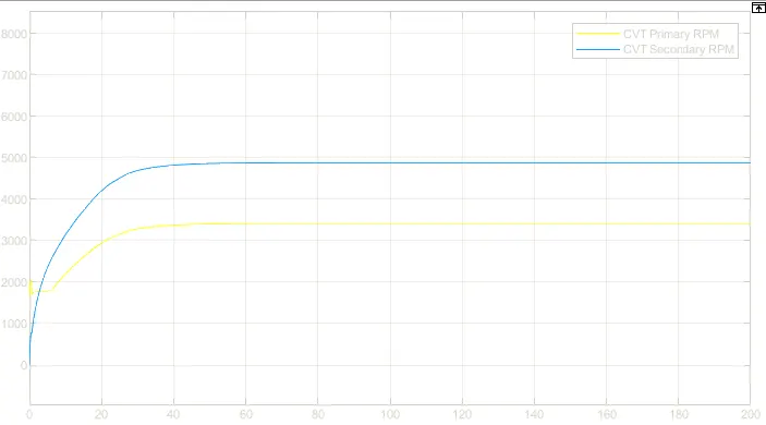
Fig 5: Graphical Representation of two pulleys in CVT
Vehicle Body
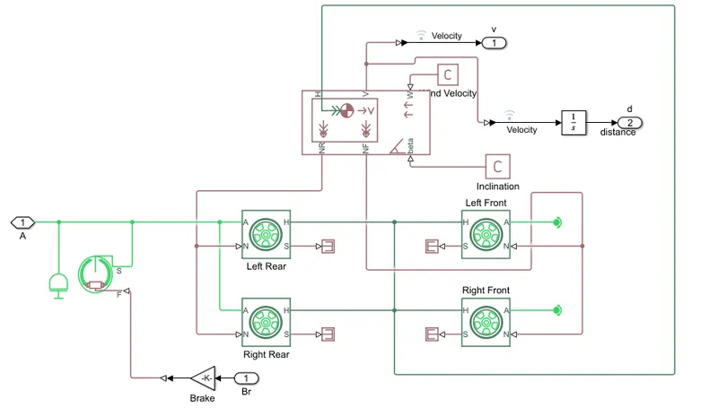
Fig 6: Subsystem of Vehicle Body
The Major blocks used in building the vehicle body
- Inertia - The block represents an ideal mechanical rotational inertia. The block has one or two mechanical rotational conserving ports.
- Double Shoe Brake - Represents a brake arranged as two pivoted rigid shoes symmetrically installed inside or outside a drum and operated by one actuator.
- Tire - Represents the longitudinal behaviour of a highway tire characterized by the tire Magic Formula.
- Vehicle Body Block - Represents a two-axle vehicle body in longitudinal motion. The block accounts for body mass, aerodynamic drag, road incline, and weight distribution between axles due to acceleration and road profile. The vehicle can have the same or a different number of wheels on each axle. Optionally include pitch and suspension dynamics or additional variable mass and inertia. The vehicle does not move vertically relative to the ground.
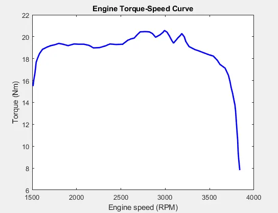
Fig 7: Graph of Engine Speed VS Torque
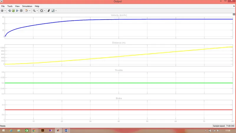
Fig 8: Graph of Velocity – Distance – Torque – Brake
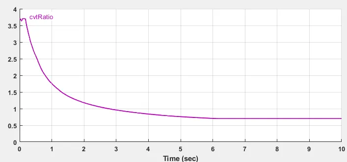
Fig 9: CVT Ratio of the Model
Simulink Model of BAJA ATV model with Dash Board System
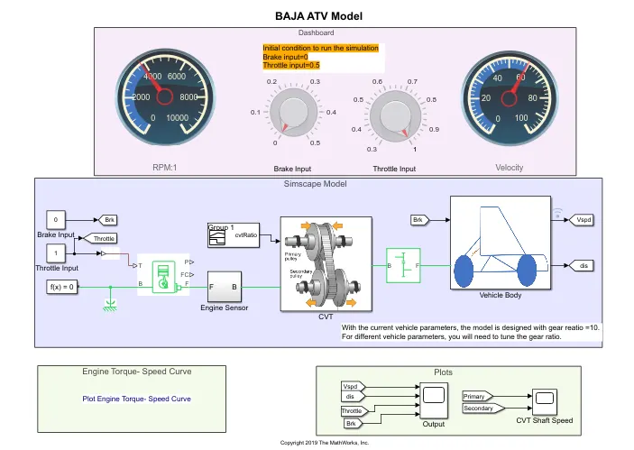
Fig 10: BAJA ATV Model with Dash Board
The above simulink model uses as dashboard system instead of using a signal builder block. The Brakes and Throttle input is provided using Knob. The main usage of using dashboard is to vary the brake and throttle input during the simulation.
Result of a Different study
The result of the below study of the BAJA ATV model using CVT system is when the Throttel of the vehicle is increased suddenly to gain velocity.
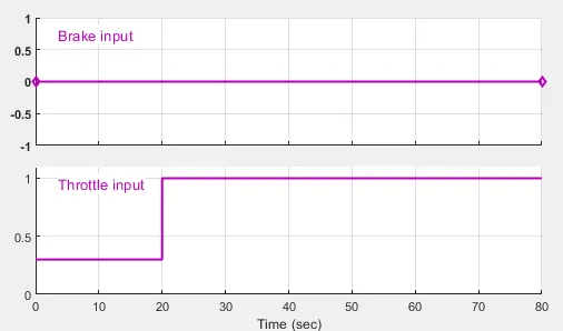 (Brakes are not applied and throttle has been incresed from 0.25-1)
Fig 11: Throttle input is varied
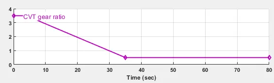 (The Gear Ratio of Two CVT system is ruduced inversly to throttle)
Fig 12: CVT Gear Ratio Reduce as Throttle increases
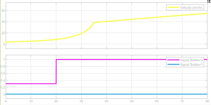
Fig 13: As The gear ratio decreses the Velocity Increses
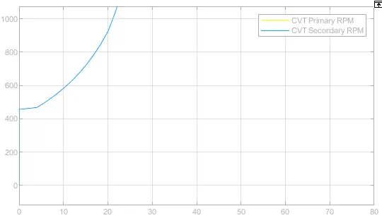
Fig 14: As Velocity increses the RPM of Secondary CVT increases to maximum
CONCLUSION
- The stating torque of the ATV model is high comapared to traditional vehicles.
- As throttle increses, the velocity also increses which produces more power.
- By applaying brakes, the velocity of the vehicle decreses w.r.t power.
- As the gear ratio increses, torque increases.
- As the velocity of the vehicle increases the torque of the vehicle resuces which inturn increses the staility of the vehicle.
- The velocity of the vehicle is changed with respect to the gear ratio of the CVT system.
- The high gear ratio, the torque is which reduces the velocity.
- The low gear ratio provides more is when the vehicle is at high velocity.
Studied about the BAJA ATV model vehicle which uses Continues Variable Transmission System(CVT).
This study helps to understand the advantage of using system level simulation model inorder to find specific character and parameter of diffenerence components.
Referenece
https://in.mathworks.com/help/matlab/