Week-7 Challenge: DC Motor Control
1. A. Explain a MATLAB demo model named ‘Speed control of a DC motor using BJT H-bridge’.
B. Comment on the armature current shoot-up from the scope results.
C. Refer to the help section of ‘The Four-Quadrant Chopper DC Drive (DC7) block’. Compare it with the H-bridge model.
DC motor using BJT H-bridge:-
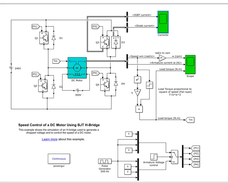
This model consists of a H bridge with 4BJT_Diode Pair.
The inputs such as duty cycle and step time given from pilse generator block Armature Voltage control Block.
The Bipolar Junction Transistor (BJT) when used for power switching applications, operates as an IGBT.
When it is conducting (BJT operating in the saturated region), a forward voltage Vf is developed between collector and emitter (in the range of 1 V).
Therefore, the IGBT block can be used to model the BJT device.
The IGBT block does not simulate the gate current controlling the BJT or IGBT.
The switch is controlled by a Simulink® signal (1/0).
The DC motor uses the preset model (5 HP 24V 1750 rpm).
It simulates a fan type load (where Load torque is proportional to square of speed).
The armature mean voltage can be varied from 0 to 240 V when the duty cycle (specified in the Pulse Generator block) is varied from 0 to 240 V when the duty cycle (specified in the Pulse Generator block) is varied from 0 to 100%.
Simulation output:-
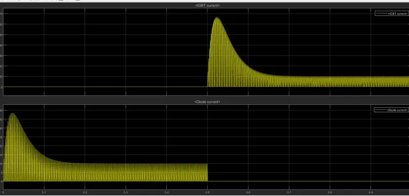
The avove graphs shows the current passing through IGBT and diode.so for 0 to 0.5 sec current is flowing through the diode D3 and 0.5 to 1sec the current is passing through Q3.here load torque is proportional to the square of angular velocity.
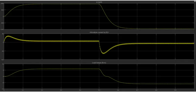
B. Comment on the armature current shoot-up from the scope results.
The principle of pulse width modulation.The advantage value of voltage of voltage fed to load is controlled by turning the switch between supply and load on and off at a fast rate.The PWM switching frequency has to be high enough not to affect the load which is to say that the result waveform perceved by the load must be as smooth as possible.
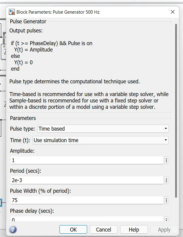
The folloeing plot shows the output when the PWM value is changed.
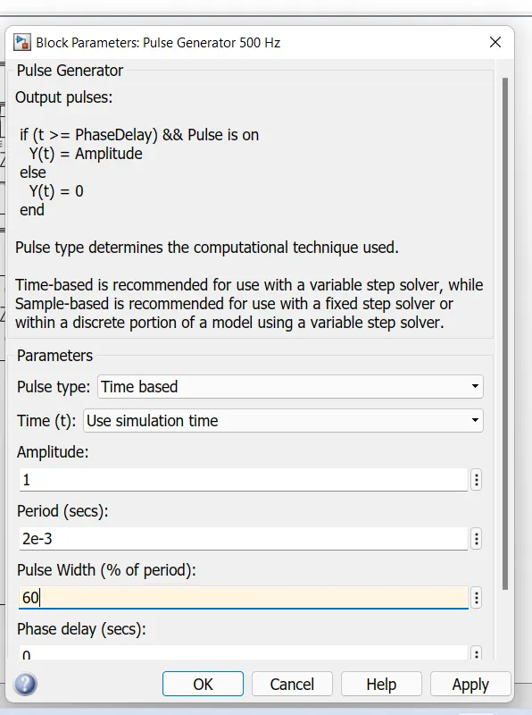
Then the same time we can change PWM value inthe pulse width is 60 then we can check the output of aArmature and load torque and rpm.
The folloeing plot shows the output when the PWM value is changed.
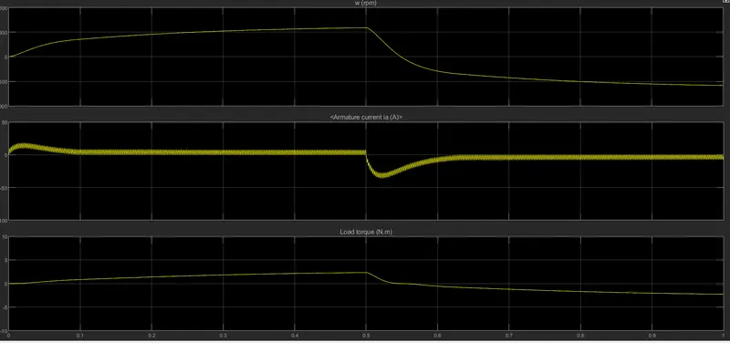
As duty cycle is reduced to 40% there is no sudden peak in the output.
C. Refer to the help section of ‘The Four-Quadrant Chopper DC Drive (DC7) block’. Compare it with the H-bridge model.
The Four-Quadrant Chopper DC Drive (DC7) block:-
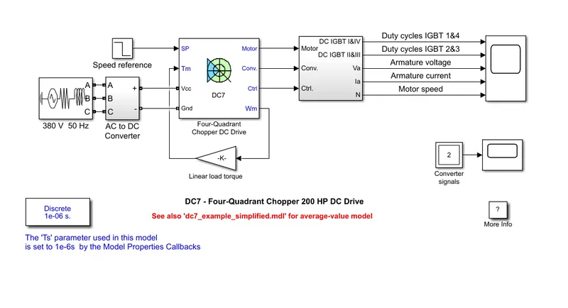
The 200 HP DC motor is separately excited with a constant 150 V DC field voltage source. The armature voltage is provided by an IGBT converter controlled by two PI regulators.
The converter is fed by a 515 V DC bus obtained by rectification of a 380 V AC 50 Hz voltage source. In order to limit the DC bus voltage during dynamic braking mode, a braking chopper has been added between the diode rectifier and the DC7 block.
The first regulator is a speed regulator, followed by a current regulator.
The speed regulator outputs the armature current reference (in p.u.) used by the current controller in order to obtain the electromagnetic torque needed to reach the desired speed.
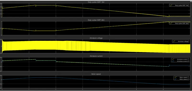
The speed reference change rate follows acceleration and deceleration ramps in order to avoid sudden reference changes that could causes.
Simulation output:-
Four Quadrant Operation:-
The four quadrant operation of the motor can be described as follows −
Quadrant I:-
In the first quadrant, the developed power by the motor is positive, thus the motor operates in motoring mode and converts electrical energy into mechanical energy. Therefore, the operation of the motor in first quadrant is called forward motoring.
Quadrant II:-
In the second quadrant, the direction of the rotation is positive i.e. speed is positive and the torque is negative. Hence, the developed power is negative and the machine operates as a generator which opposes its motion. The kinetic energy of the moving parts of the machines is converted into electrical energy. Therefore, the operation of motor in second quadrant is called forward breaking.
Quadrant III:-
In the third quadrant, the motor speed and torque both are negative, hence the power is positive. Therefore, the operation of the motor in the third quadrant is known as reverse motoring.
Quadrant IV:-
In the fourth quadrant, the motor speed is negative and the developed torque is positive, hence the motor power is negative which is corresponding to the breaking operation. Therefore, the operating in fourth quadrant is known as reverse breaking.
The four quadrant operation of the motor can be summarised in the figure shown below.

2. Develop a 2-quadrant chopper using simulink & explain the working of the same with the relevant results. (Refer to article - Multiquadrant operation of motor )
Chopper-Fed DC Motor Drive:-
D.C motor is considered a SISO (Single Input and Single Output) system having torque/speed characteristics compatible with most mechanical loads. This makes a DC motor controllable over a wide range of speeds by proper adjustment of the terminal voltage
A simple chopper – fed DC motor drive is shown in Fig.2. The basic principle behind DC motor speed control is that the output speed of a DC motor can be varied by controlling armature voltage for speed below and up to rated speed keeping field voltage constant. The armature voltage can be controlled by controlling the duty cycle of the converter (here the converter used is a DC chopper)
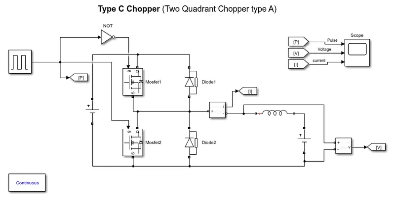
The above model is the model of Type Chopper(Type A Two Quadrant Chopper). In this type of Chopper, the average voltage will be always positive but the average load current might be positive or negative. The two Switches CH1 and CH2 should not be turned on simultaneously as the combined action may cause a short circuit in supply lines. For regenerative braking and motoring these type of chopper configuration is used.
We will always get a positive output voltage V0 as the freewheeling diode FD is present across the load. When the chopper CH1 is on the current flows from source to load. The inductor stores energy. When Ch1 turn OFF the freewheeling diode starts conducting and the output voltage v0 will be equal to Vs. The direction of the load current i0 will be reversed. The current i0 will be flowing towards the source. The load current will be negative when the CH2 is on. The current completes its path through diode D2.
Simulation model:-
Output:-
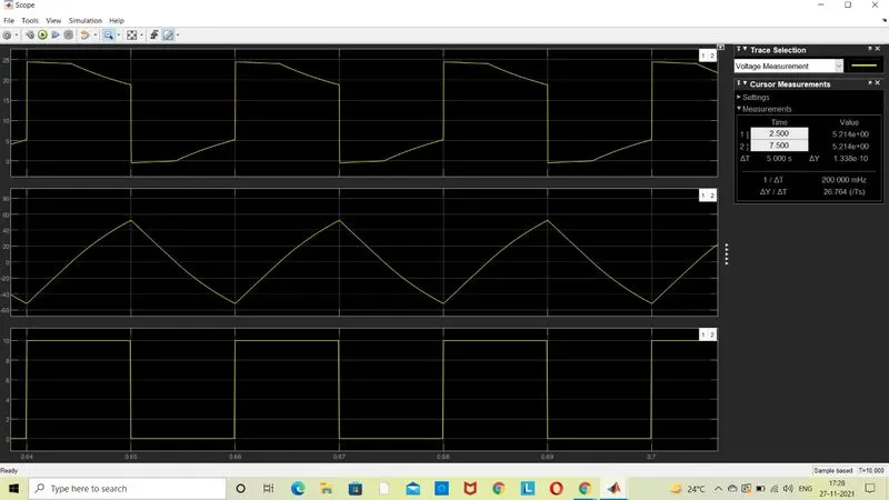
3. Explain in a brief about operation of BLDC motor.
Brushless Motor:-
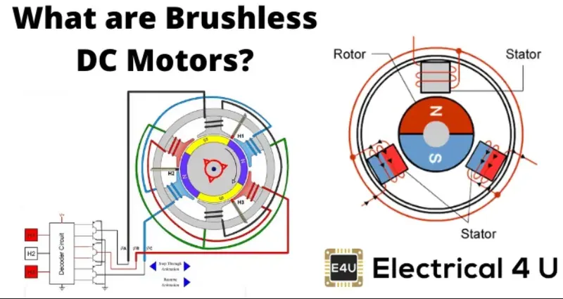
A brushless DC motor (also known as a BLDC motor or BL motor) is an electronically commuted DC motor which does not have brushes.
The controller provides pulses of current to the motor windings which control the speed and torque of the synchronous motor.
These types of motors are highly efficient in producing a large amount of torque over a vast speed range.
In brushless motors, permanent magnets rotate around a fixed armature and overcome the problem of connecting current to the armature.
Commutation with electronics has a large scope of capabilities and flexibility. They are known for smooth operation and holding torque when stationary.
Brushless Motor Work:-
Before explaining the working of a brushless DC motor, it is better to understand the function of a brushed motor.
In brushes motors, there are permanent magnets on the outside and a spinning armature which contains electromagnet is inside.
These electromagnets create a magnatic field in the armature when the power is switched on and help to rotate the armature.
The brushes change the polarity of the pole to keep the rotation on of the armature.
The basic working principle for the brushed DC motor and for brushless DC motor are same i.e. internal shaft position feedback.
Brushless DC motor has only two basic parts: -
rotor and the stator. The rotor is the rotating part and has rotor magnets whereas stator is the stationary part and contains stator windings.
In BLDC permanent magnets are attached in the rotor and move the electromagnets to the stator.
The high power transistors are used to activate electromagnets for the shaft turns.
The controller performs power distribution by using a solid-state circuit.
Types of Brushless DC Motors:-
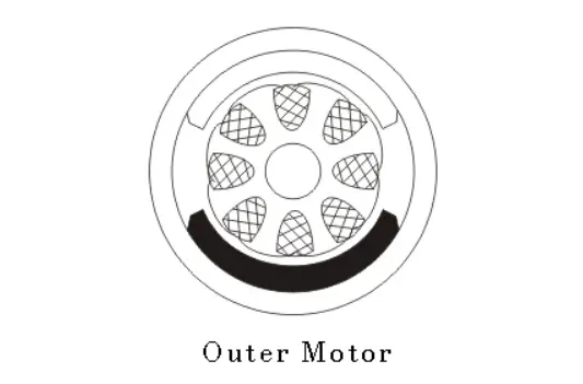
Basically, BLDC are of two types, one is outer rotor motor and other is inner rotor motor.
The basic difference between the two is only in designing, their working principles are same.
Inner Rotor Design:-
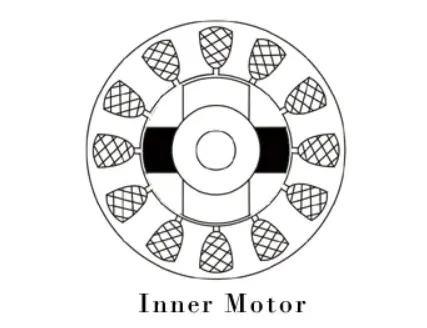
In an inner rotor design, the rotor is located in the centre of the motor and the stator winding surround the rotor. As the rotor is located in the core, rotor magnets do not insulate heat inside and heat get dissipated easily. Due to this reason, inner rotor designed motor produces a large amount of torque and validly used.
Outer Rotor Design:-
In outer rotor design, the rotor surrounds the winding which is located in the core of the motor. The magnets in the rotor trap the heat of the motor inside and do not allow to dissipate from the motor. Such type of designed motor operates at lower rated current and has low cogging torque.
The advantages of a BLDC motor are:-
- Brushless motors are more efficient as its velocity is determined by the frequency at which current is supplied, not the voltage.
- As brushes are absent, the mechanical energy loss due to friction is less which enhanced efficiency.
- BLDC motor can operate at high-speed under any condition.
- There is no sparking and much less noise during operation.
- More electromagnets could be used on the stator for more precise control.
- BLDC motors accelerate and decelerate easily as they are having low rotor inertia.
- It is high performance motor that provides large torque per cubic inch over a vast sped rang.
- BLDC motors do not have brushes which make it more reliable, high life expectancies, and maintenance free operation.
- There is no ionizing sparks from the commutator, and electromagnetic interference is also get reduced.
- Such motors cooled by conduction and no air flow are required for inside cooling.
The disadvantages of a BLDC motor are:-
- BLDC motor cost more than a brushed DC motor.
- The limited high power could be supplied to BLDC motor, otherwise, too much heat weakens the magnets and the insulation of winding may get damaged.