Week - 4
Implement control logic of a “washing machine” using Stateflow as per given sequence:
- If the power supply is available, the system gets activated
- If the Water supply is not available, stop the process & indicate through LED
- Soaking time should be 200s followed by Washing time of 100s.
- Then rinsing happens for next 20s & dryer runs for 50
Aim:-
Implement control logic of a “washing machine” using Stateflow as per given sequence.
Blocks are used:-
chart box
state
constant
display
lamp
working principle:-
The working principle of a washing machine is centrifugation. Centrifugation is a separation process that uses the action of centrifugal force to promote accelerated settling of particles in a solid-liquid mixture.
Soaking:-
Light, wispy soaking coming from the bottom of the washing machine indicates a problem with the transmission shifting solenoid. Smoke coming from the upper back of the machine indicates a bad fill valve solenoid. And smoke coming from the control panel indicates a bad timer motor.
Washing:-
During the wash cycle a large plastic a gitator turns around moving your cloths through the water.
Rinsing:-
The dircty,scopy water is draineed,then the wasing machine is refilled and your cloths through the rewashed in clean water.
Dryer:-
They work by pusing warm dry air through you wet washing to extract moisture then cooling now humid air in a heat exchange to condense the moisture.
Control logic:-
It checks for the extent of drift and grease the amount of soap and water to add water and dirction of spin and so on. The machine rebalance washing load to ensure correct spining else we reduces spinning speed it can in balance is detected.Then washing load reduces spinning Noise.
The system are observed to sometime and we check and procced to completed by the system.then the green light as displayed on results on the screen.
Simulation model:-
In chart box
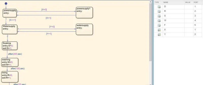
The above model is the process in the internal process of the circuit.
IN ON POSITION :-
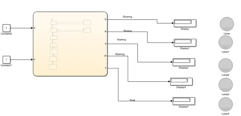
IN OFF POSITION:-
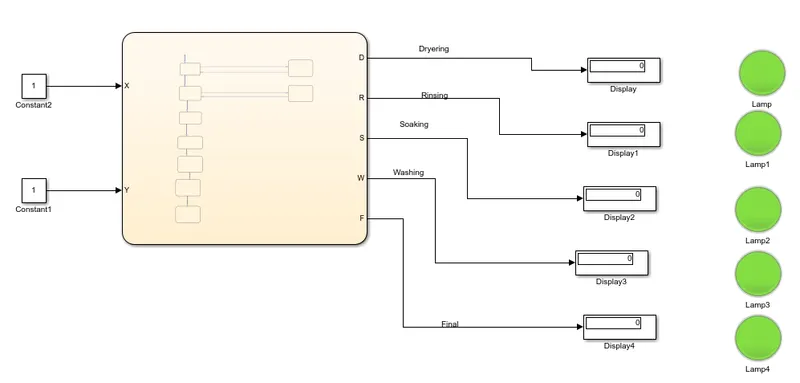
The above model is the final output of the control logic of a “washing machine” using Stateflow of the system.
Make a Simulink chart for the “Gear shift” logic as per below conditions:
Speed Range(kmph) Gear
0 to 15 1
16 to 25 2
26 to 40 3
41 to 60 4
Above 61 5
Give speed input while the simulation is running & display the gear number.
Aim:-
Make a Simulink chart for the “Gear shift”.
Blocks are used:-
Slider block
constant
display
chart block
Explanation:-
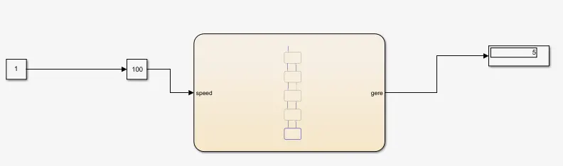
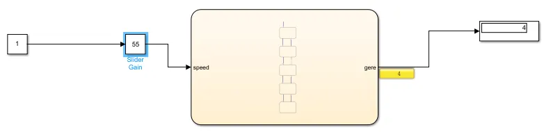
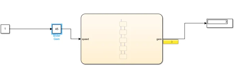
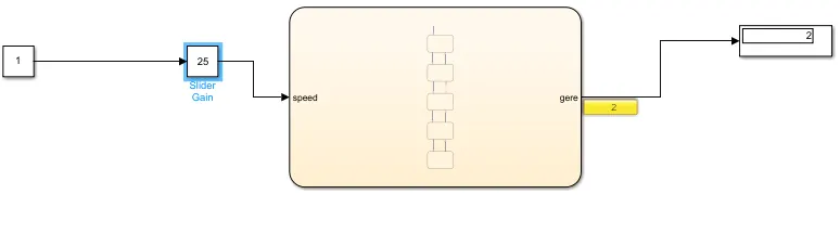
In this system gives the speed range is 0-100 so,we use slider block for the given input speed.The frist gear speed rang is 0-15 so,the entery of state for the 1st gear is 0<=speed range and the 15>= speed range.It is the exiting conditions of gear in speed.In secong gear entery state 16<=speed rangeand 25>= speed range..It is the exiting conditions of gear in speed. Then the same time we have a remaining three gears are left in each gare have a different speed are there so,we can set the chart box enter the vallues like speed is the input and the the gear is the outout.
The above chart the gear transition is decided below ranges.
Speed Range(kmph) Gear
0 to 15 1
16 to 25 2
26 to 40 3
41 to 60 4
Above 61 5
Simulation model:-
in chart box
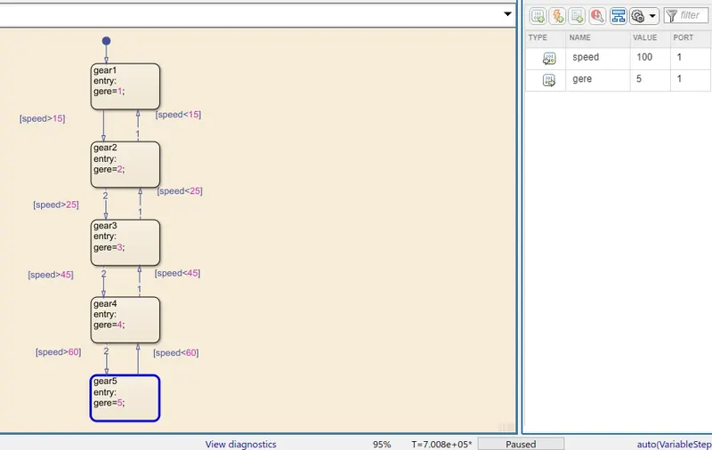
ouput model and result:-
5th gear:-
4th gear:-
3rd gear:-
2nd gear:-
1st gear:-
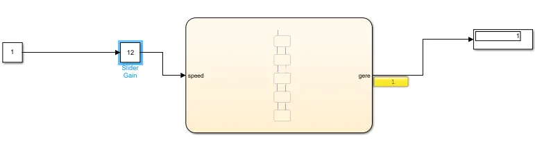
To varry the slider vallues then the gears will changes.