Week-6 Challenge: EV Drivetrain
1) Which types of power converter circuits are employed in electric and hybrid electric vehicle?
The different configurations of EV power supply show that at least one DC/DC converter is necessary to interface the FC, the Battery or the Supercapacitors module to the DC-link.
DC -DC converters:-
In electric engineering, a DC to DC converter is a category of power converters and it is an electric circuit which converts a source of direct current (DC) from one voltage level to another, by storing the input energy temporarily and then releasing that energy to the output at a different voltage.
DC/DC converters can be designed to transfer power in only one direction, from the input to the output. The amount of power flow between the input and the output can be controlled by adjusting the duty cycle.
. Transformer-based converters may provide isolation between the input and the output. The main drawbacks of switching converters include complexity, electronic noise and high cost for some topologies.
Non-isolated converters:-
The non-isolated converters type is generally used where the voltage needs to be stepped up or down by a relatively small ratio.
There are five main types of converter in this non-isolated group, usually called the buck, boost, buck-boost, Cuk and charge-pump converters.
The buck converter is used for voltage step-down.
while the boost converter is used for voltage step-up.
The buck-boost and Cuk converters can be used for either step-down or step-up.
The charge-pump converter is used for either voltage step-up or voltage inversion, but only in relatively low power applications.
Isolated converters:-
Usually, in this type of converters a high frequency transformer is used. In the applications where the output needs to be completely isolated from the input, an isolated converter is necessary.
There are many types of converters in this group such as Half-Bridge, Full-Bridge, Fly-back, Forward and Push-Pull DC/DC converters.
All of these converters can be used as bi-directional converters and the ratio of stepping down or stepping up the voltage is high.
2) An Electric Vehicle's powertrain with 72V battery pack in shown in the diagram below. The duty ratio for acceleration operation is 'd1' and for the braking operation the duty ratio is 'd2'.
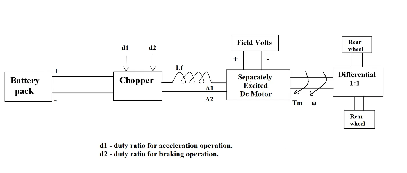
The other parameters of the electric vehicle is given below,
Motor and Controller Parameters:
Rated Armature voltage= 72 V
Rated armature current= 400 A
Ra= 0.5Ω, KΦ= 0.7 Volt second
Chopper Switching frequency= 400 Hz
The vehicle speed-torque characteristics are given by the below equation

What is EV steady state speed if duty cycle is 70%?
Given that data:-
Motor and Controller Parameters:
Rated Armature voltage= 72 V
Rated armature current= 400 A
Ra= 0.5Ω, KΦ= 0.7 Volt second
Chopper Switching frequency= 400 Hz
The vehicle speed-torque characteristics are given by the below equation
Battery pack voltage(v) = 72
Ratel armature current =400A
Armature resistance (Ra)= 0.5
Motor constant=0.7
Chopper switching frequency =400 hz
Duty cycle = 70%
Vehicle output voltage (V) =Battery voltage(V) * Duty cycle
= 72*0.70 = 50.4 V
Vehicle voltage = 50.4 V
Vehicle Torque = Tv=
Where
Tv =vehicle torque(N-m)
Vv = vehicle voltage(v)
W=Steady state speed of vehicle(rps)
KΦ= Motor constant
Ra = Armature resistance
Subsutting all the values in equaction ----------1
Tv =50.4*0.70/0.5 –(0.7)^2/(0.5)*w
Tv = 70.56 -0.98 w^2 ----------2
Now the vehicle speed torque characteristics is given as
Tv =24.7 -0.0051 w^2 -------3
At stady state
Equaction 2 = Equaction 3 ----4
24.7-0.0051 w^2 =70.56-0.98 w^2
0.0051w^2+0.96 w -45.85 =0 --------5
To slove the above equaction we have to applythe Quadartic equaction formula
(-b±√(b²-4ac))/(2a)
X= (-0.98±√((0.98)²-4(0.00056)(-45.85)/2(0.0051)
X=38.92 rad/sec
3) Develop a mathematical model of a DC Motor for the below equation using Simulink.
Simulation model:-
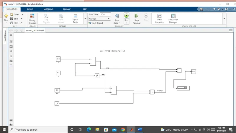
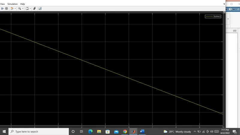
Output:-
4) Refer to the blog on below topic:
Induction Versus DC brushless motors by Wally Rippel, Tesla
Explain in brief about author’s perspective.
DC brushless drives.:-
The brushless machines, the rotor includes two or more permanent magnets that generate a DC magnetic field.
There are Two parts are main in the brushes that is core and torque.
Core:-
In turn, this magnetic field enters the stator core and interacts with currents flowing within the windings to produce a torque interaction between the rotor and stator.
The device that provides this current control is called an inverte. Without it, brushless motors are useless motors.
3-phase induction motor:-
A forerunner of the 3-phase induction motor was invented by Nikola telsa sometime before 1889. Curiously, the stators for the 3-phase induction motor and the DC brushless motor are virtually identical. Both have three sets of “distributed windings” that are inserted within the stator core. The essential difference between the two machines is with the rotor.
While 3-phase induction motors have great utility, they also have some severe limitations. They cannot operate from DC; AC is a must. Shaft speed is proportionate to line frequency. Hence, when used with utility power, they are constant speed machines.
Today, all the hybrids are powered by DC brushless drives, with no exceptions. The only notable uses of induction drives have been the General motor EV-1 the AC propulsion vehicles, including the tzero; and the Tesla Roadster.
Induction machines are more difficult to control. The control laws are more complex and difficult to understand. Achieving stability over the entire torque-speed range and over temperature is more difficult with induction than with DC brushless. This means added development costs, but likely little or no recurring costs.
My conclusion is that DC brushless drives will likely continue to dominate in the hybrid and coming plug-in hybrid markets, and that induction drives will likely maintain dominance for the high-performance pure electrics.