Week-7 Challenge: DC Motor Control
Question 1 A). Explain a MATLAB demo model named ‘Speed control of a DC motor using BJT H-bridge’.
First let us understand the basic concept of speed control using H bridge configuration.
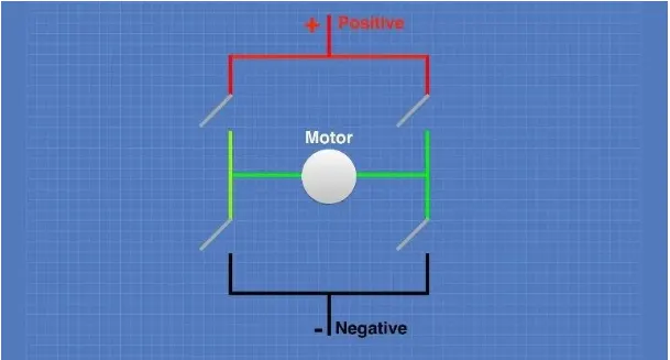
An “H-Bridge” is simply an arrangement of switching the polarity of the voltage applied to a DC motor, thus controlling its direction of rotation. To visualize how this all works I’ll use some switches, although in real life an H-Bridge is usually built using transistors. Using transistors also allows you to control the motor speed with PWM, as described above.
In the first diagram we can see four switches which are all in the open or “off” position. In the center of the circuit is a DC motor. If you look at the circuit as it is drawn here you can distinctly see a letter “H”, with the motor attached in the center or “bridge” section – thus the term “H-Bridge”.
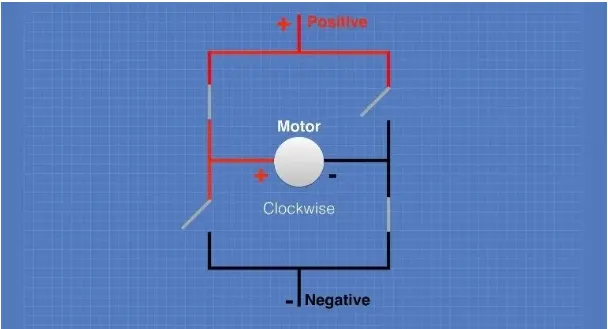
If we close (i.e. turn on) two of the switches you can see how the voltage is applied to the motor, causing it to turn clockwise.
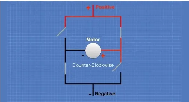
Now we’ll open those switches and close the other two. As you can see this causes the polarity of the voltage applied to the motor to be reversed, resulting in our motor spinning counterclockwise.
H-Bridge built by transistor for controlling DC motor speed and rotation
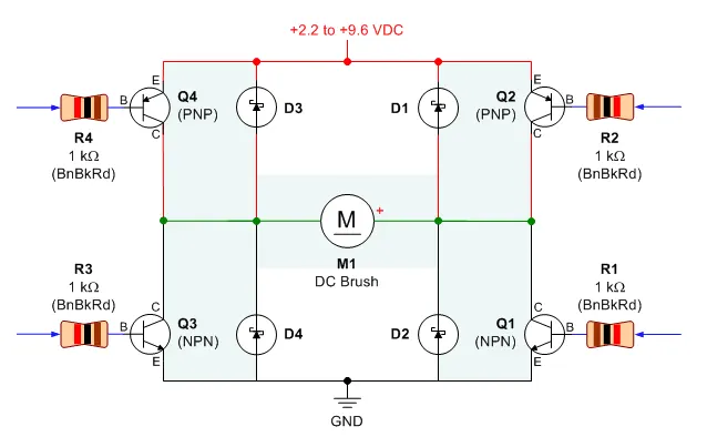
- Q1, Q3: These are NPN transistors. They connect the motor to ground (negative terminal of the battery).
- Q2, Q4: These are PNP transistors. They connect the motor to +2.2V to +9.6V (positive terminal of the battery).
- R1-R4: These resistors prevent too much current from passing through the base (labeled B) control pin of the transistor.
- D1-D4: Diodes provide a safe path for the motor energy to be dispersed or returned to the battery when the motor is commanded to coast or stop. Without diodes, a motor voltage spike can force its way through the unprotected transistors, damaging or destroying them.
- M1: This is a direct-current (DC) motor.
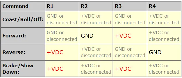
Now, Controlling the H-Bridge Motor driver.
The resistors are the inputs that control the H-bridge. By connecting a resistor to either +VDC or GND, it turns on or off the corresponding transistor. (+VDC is the positive end of the battery. GND is the negative end of the battery.) When a particular pair of transistors is turned on, the motor does something.
Simulink Model of H-Bridge used to generate a chopped voltage and to control the speed of a DC Motor
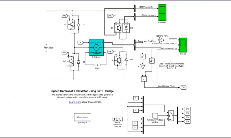
The Bipolar Junction Transistor (BJT) when used for power switching applications, operates as an IGBT. When it is conducting (BJT operating in the saturated region), a forward voltage Vf is developed between collector and emitter (in the range of 1 V). Therefore, the IGBT block can be used to model the BJT device.
The IGBT block does not simulate the gate current controlling the BJT or IGBT. The switch is controlled by a Simulink® signal (1/0). The DC motor uses the preset model (5 HP 24V 1750 rpm). It simulates a fan type load (where Load torque is proportional to square of speed). The armature mean voltage can be varied from 0 to 240 V when the duty cycle (specified in the Pulse Generator block) is varied from 0 to 100%.
The H-bridge consists of four BJT/Diode pairs (BJT simulated by IGBT models). Two transistors are switched simultaneously: Q1 and Q4 or Q2 and Q3. When Q1 and Q4 are fired, a positive voltage is applied to the motor and diodes D2-D3 operate as free-wheeling diodes when Q1 and Q4 are switched off. When Q2 and Q3 are fired, a negative voltage is applied to the motor and diodes D1-D4 operate as free-wheeling diodes when Q2 and Q3 are switched off.
Question 1 B) Comment on the armature current shoot-up from the scope results.
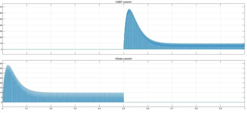
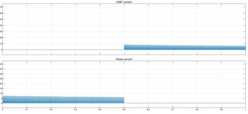
In the results scope, we can observe that after 0.5 seconds the IGBT current starts flowing.
The current starts flowing in diode upto 0.5 seconds
There is no passage of diode current which indicates that current may passing in reverse direction.
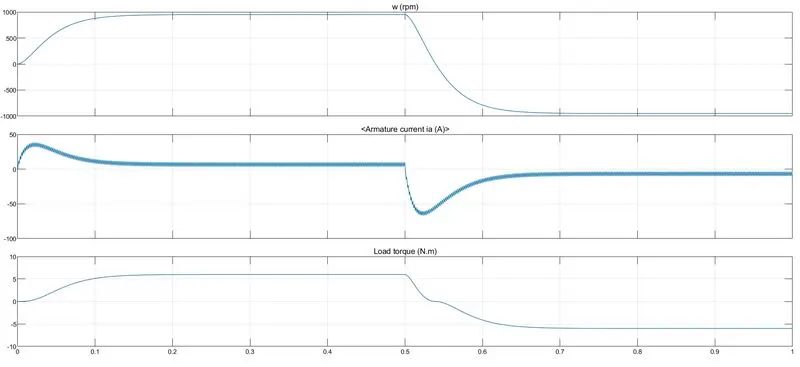
- Initially, we observed that the speed is increased to top and maintains upto 0.5 seconds. After that it is reduced and goes to negative.
- After 0.5 seconds we can observe armature current shoots up.
- The load also decreases after 0.5 seconds.
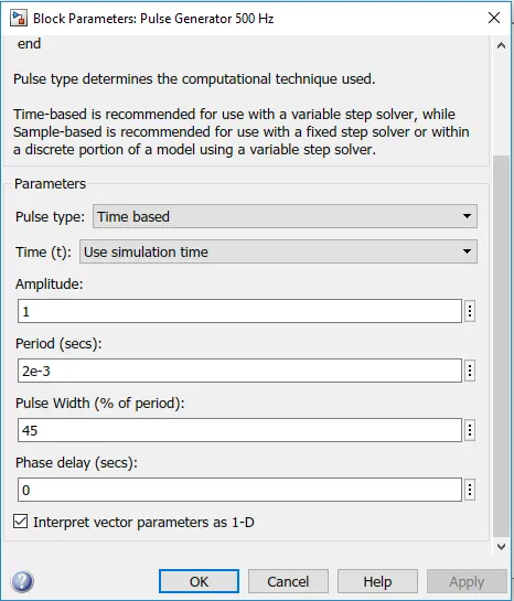
Now, Changing the duty cycle, So that the motor changes its direction from forward to reverse and armature current doesn't shoot up. Changing pulse width from 75% to 45%.
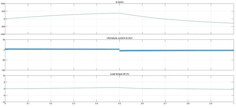
Results after changing pulse width:
- we observe that the armature current doesnt shoots up.
- Instead of sudden decrease there is a slow decrease in speed and load torque after 0.5 seconds.
- Variations are less as compared to previous case
Question 1 C) Refer to the help section of ‘The Four-Quadrant Chopper DC Drive (DC7) block’. Compare it with the H-bridge model.
The Four-Quadrant Chopper DC Drive (DC7) block represents a four-quadrant, DC-supplied, chopper (or DC-DC PWM converter) drive for DC motors. This drive features closed-loop speed control with four-quadrant operation. The speed control loop outputs the reference armature current of the machine. Using a PI current controller, the chopper duty cycle corresponding to the commanded armature current is derived. This duty cycle is then compared with a sawtooth carrier signal to obtain the required PWM signals for the chopper.
The main advantage of this drive, compared with other DC drives, is that it can operate in all four quadrants (forward motoring, reverse regeneration, reverse motoring, and forward regeneration). In addition, due to the use of high switching frequency DC-DC converters, a lower armature current ripple (compared with thyristor-based DC drives) is obtained. However, four switching devices are required, which increases the complexity of the drive system.
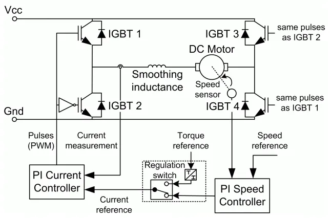
The Four-Quadrant Chopper DC Drive block uses these blocks from the Electric Drives/Fundamental Drive Blocks library:
-
Speed Controller (DC)
-
Regulation Switch
-
Current Controller (DC)
-
Chopper
Comparison of H bridge with 4 quadrant chopper DC drive.
| H Bridge | Four quadrant chopper DC drive |
| Only two quadrants of operation are possible. They are forward motoring and reverse motoring. | It can operate in all four quadrants (forward motoring, reverse generation, reverse motoring, and forward regeneration) |
| Higher armature current ripple. | Lower armature current ripple due to high switching frequency of DC-DC converters |
| Less complex | More coimplex |
| Simulation is continuous and simulation time is more | Discrete and Simulation time is less |
| Widely used in robotics | Widely used in automobile |
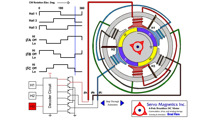
Question 3) Explain in a brief about operation of BLDC motor.
A brushless DC electric motor (BLDC motor or BL motor), also known as an electronically commutated motor (ECM or EC motor) or synchronous DC motor, is a synchronous motor using a direct current (DC) electric power supply. It uses an electronic controller to switch DC currents to the motor windings producing magnetic fields which effectively rotate in space and which the permanent magnet rotor follows. The controller adjusts the phase and amplitude of the DC current pulses to control the speed and torque of the motor.
The construction of a brushless motor system is typically similar to a permanent magnet synchronous motor (PMSM), but can also be a switched reluctance motor, or an induction (asynchronous) motor.
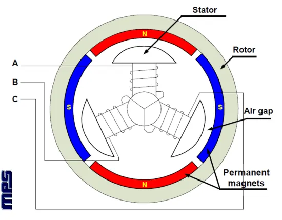
The advantages of a brushless motor over brushed motors are high power-to-weight ratio, high speed, nearly instantaneous control of speed (rpm) and torque, high efficiency, and low maintenance.
Disadvantages of brushed motor:
The commutator has disadvantages that has led to a decline in use of brushed motors. These disadvantages are:
- The friction of the brushes sliding along the rotating commutator segments causes power losses that can be significant in a low power motor.
- The soft brush material wears down due to friction, creating dust, and eventually the brushes must be replaced. This makes commutated motors unsuitable for low particulate or sealed applications like hard disk motors, and for applications that require maintenance-free operation.
- The electrical resistance of the sliding brush contact causes a voltage drop in the motor circuit called brush drop which consumes energy.
- The repeated abrupt switching of the current through the inductance of the windings causes sparks at the commutator contacts, which is a fire hazard in explosive atmospheres and a source of electronic noise, which can cause electromagnetic interference in nearby microelectronic circuits.
In brushless DC motors, an electronic servo system replaces the mechanical commutator contacts. An electronic sensor detects the angle of the rotor and controls semiconductor switches such as transistors which switch current through the windings, either reversing the direction of the current or, in some motors turning it off, at the correct angle so the electromagnets create torque in one direction.
Brushed DC motors develop a maximum torque when stationary, linearly decreasing as velocity increases. Some limitations of brushed motors can be overcome by brushless motors; they include higher efficiency and lower susceptibility to mechanical wear.
A typical brushless motor has permanent magnets that rotate around a fixed armature, eliminating problems associated with connecting current to the moving armature. An electronic controller replaces the commutator assembly of the brushed DC motor, which continually switches the phase to the windings to keep the motor turning.
When converting electricity into mechanical power, brushless motors are more efficient than brushed motors primarily due to the absence of brushes, which reduces mechanical energy loss due to friction. The enhanced efficiency is greatest in the no-load and low-load regions of the motor's performance curve.