Week-7 Challenge: DC Motor Control
Challenge 1-
{A}
In the model we uses H-bridge circuit to control the DC motor where we uses IGBT as a switching deviceand input to this IGBT is given by a control circuit appearing in the bottom of the model such that for 0.5 seconds P1,P2 will be active and P2,P3 will be inactive and after 0.5 sec the control signal changes to P1,P4 as inactive and P2,P3 as active
so for the 0.5sec the voltage across DC motor will be positive and for next 0.5 sec voltage reverses across the armature and the avg voltage across DC motor depends on the duty cycle (75% in this case) of pulse generator block (500Hz).
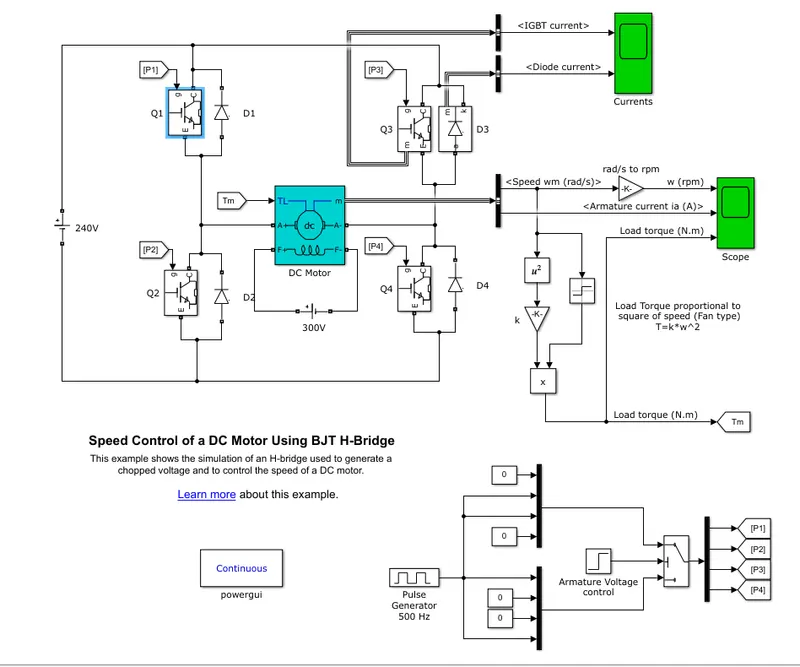
after seeing the circuit we can say that load torque will follow square law like in the case of fan i.e. `T=k*omega^2`
Now lets simulate the model for 1 secand see the results-
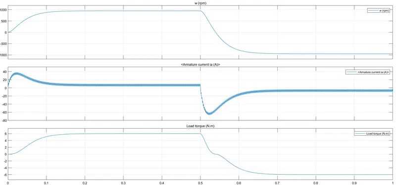
here we can see the motor starts from zero and achieve around 1000RPM of speed then after 0.5 seconds the motor starts deaccelerating and starts run in the opposite direction as voltage across motor reversed.
the ripple in armature current is due to switching on and off of the IGBT with duty cycle of 75% so for 75% of times IGBT conducts and Diode conducts for 25% of the time. In addition the armature current is continous in nature due to armature inductance, where as current in the diode and IGBT are discontinous in nature because it conducts alternately according to the duty cycle.
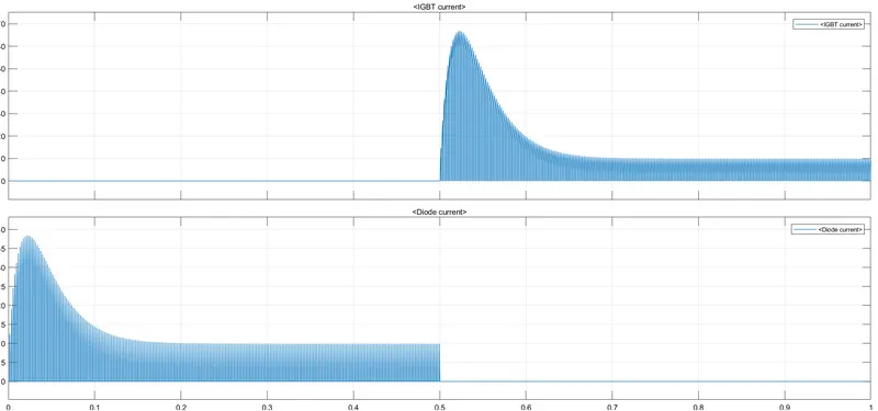
The torque follows square law with the sign. so we can conclude that we succesfully controlled the DC motor in both side where conducting of IGBT means motoring and conduction of diode means regenrative actionas it charges the source(negative current).
{B}
The shoot up of the armature current is due to starting phenomenon of the DC motor.
In the starting, when we apply voltage across DC motor, the current increases drastically as there is no back emf present in the starting..
I= V-Eb/Ra
so in starting current rises should instantaniously shoot up as Eb=0 but its not the way like we see in the graph, it is due to armature inductance that does not allow sudden change of current so current follows a exponential rise pattern and achieve a peak value than it decreases as time increases.
I= V-Eb/(Ra+sL)............. (in laplace form)
{C}
we look at the model from the help section i.e. called "The Four-Quadrant Chopper DC Drive (DC7) block" take a look at the model first...
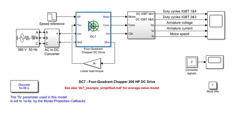
Here we can see that The DC7 Four quaderant chopper comes with both power electronics parts and DC motor itself so its called the DC Drive. but in case of H-bridge, it does not include DC motor or any control circuitary.
In DC7, Inputs are REference torque and speed data and ouputs are Chopper outputs and also DC motor outputs,Where H- bridge has only two ports i.e. input voltage and output voltage port.
we now look under the mask for DC& chopper
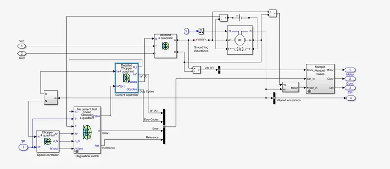
So we can see a 4 quaderant chopper connected to the DC motor which is controlled by a current controlled circuitary and it has different Speed regulating controllers.
The chopper uses PWM input that depends on the difference of the reference armature current and actual armature current and speed of Motor is directely controlled by the Duty cycle(N proportional to V) . The system include a PI controller for better regulating the output and there is no such thing available in H-Bridge converter, Even though they have similar arms of IGBT and have similar working characterstics.(DC7 has universal bridge)
Challenge 2-
2-quadrant chopper
Two quadrant operation of chopper refers to first and second quadrant of the quadratic period and it is applicable to the load having back emf or battery and load inductance. Two quadrant chopper can work with positive and negative current but voltage across load will be always positive.
we use type-B chopper where first and second quadrant are operational. if the CH1 on then the input voltage(positive) apears at the load side with current (positive) deliver to the load then if we turn off CH1 then current flows through the free wheeling diode(FD) due to load inductance.
and if we turn on the CH2 then current (negative) flows from E>L>CH2>E and voltage appears at the load is E (positive). and if we turn off the CH2 then current (negative) flows throgh the D2 due to inductance.
Now we model this scenario in the simulink environment...
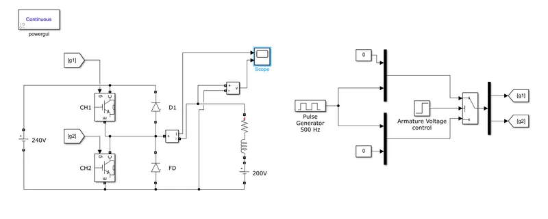
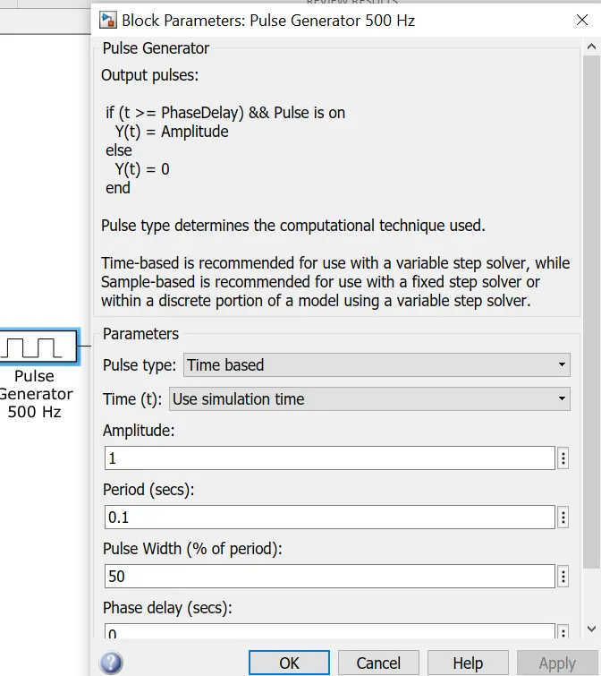
we use IGBT as the controlled switches and controlling voltage to this switches is given by a pulse generator with a selector switch (to change operating quadrants). we use 0.1sec as period time and 50% duty cycle for pulse generator.
we run the chopper in first quaderant for 0.5 sec and then change the selector switch setting after 0.5 sec and then chopper runs in the second quadarant.
now see the results that is output current and output voltage
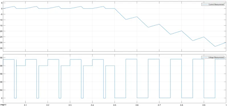
here we can see in the first 0.5 second 50% of the time input voltage(240V) appears on the load and current increases after the CH1 switch off then current flows to the FD and reduces with time constant L/R (output voltage zero). after the current become zero the voltage appears across load terminal i.e. E (200V).
in the Second quadrant operation (after 0.5s) if CH2 is on(50% of time) then output load terminal shorted(voltage=0) but current flows due to E in the load.otherwise D1 conducts and supply negative current to the source.
The reson behind current rising in the second quaderant operation is because the current rises due to 200V whereas current rises in the first quadrant is due to 240-200=40V.
Challenge 3-
BLDC Motor-
BLDC Motor works on the principle of stator and armature magnetic field locking ie. RMF. this RMF is created by an electronic control circuit called EC (Electrnic Commutator). The working of the BLDC motor is similar to the Permanent magnet synchronous motor as they both have permanent magnet rotor and space distributed stator winding and they both runs at synchronous speed. But BLDC have EC for creating a rotational magnetic field by DC supply (Power converters with angular sensors).
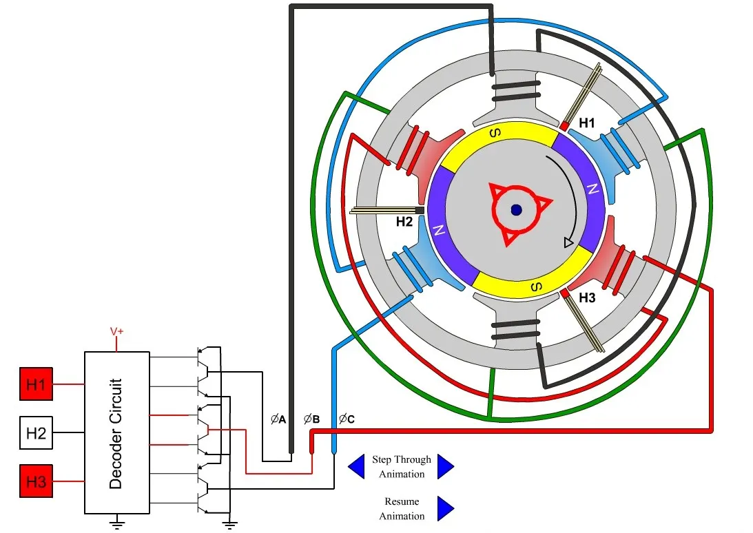
The sensors shown in figure (H1,H2,H3) are hall effect sensors and this sensors gives input to the EC decoder circuit that decodes the angular position of the rotor and gives control signal to power converter circuit to follow the sequence of pulses in order to create a Rotating magnetic field (RMF).
if we use Sinosoidal input rather than DC pulses. it is work as permanent magnet synchronous motor, The construction of PM synchronous motor is little different but we can say the working is same as BLDC motor.
BLDC motor cannot be used for high power applications due to limitation of the magnetic flus by permanent magnet. and large scale BLDC have higher core losses as compare to other motors.
The characeterstics of BLDC motor is more similar to DC motor rather than AC motors (Torque vs speed).