Week-7 Challenge: DC Motor Control
1. A. Explain a MATLAB demo model named ‘Speed control of a DC motor using BJT H-bridge’.
B. Comment on the armature current shoot-up from the scope results.
C. Refer to the help section of ‘The Four-Quadrant Chopper DC Drive (DC7) block’. Compare it with the H-bridge model.
ANS: BJT: Bipolar junction transister used to control voltage and current using the gate signal given to base emitter terminal. BJT has 2 terminals base, collecter and emmiter terminals. where load is connected to collecter terminals and is controlled by gate signals given to the base emitter. The following transistor we are using in H brigde is IGBT which is insulated gate bi polar transistor, where output is controlled by voltage signal given to gate -emitter (nearly 4v). The gate signals are controlled by PWM by duty cycle. The change in duty cycle gives us desired output what we needed.
A)
This model explains speed control of a Dc motor using bjt h bridge. The h bridge consists of 4 IGBT and 4 diodes used to run motor in forward and backward direction. When Q1 and Q2 are turned on through gate pulse the motor runs in forward direction due to forward voltage applied to it and D2 and D3 are acted as free wheeling diode. When Q3 and Q2 are turned on then negative voltage acted across the motor and runs in negatve direction while D1 and D4 are as free wheeling diode. Thus the motor speed is controlled. The gate signals are given by PWM generator that produces the pluses in synchronization.
B)
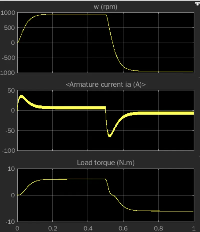
The plot of the armature current is at 75% duty cycle. At Q1 nd Q4 are trigged and D2 and D3 are operated in free wheeling diode the armature current flows in positive direction. the rise in armature current is not linear because of the inductor present in the armature circuit and same goes in the off state.
C)
Refer to the help section of ‘The Four-Quadrant Chopper DC Drive (DC7) block’. Compare it with the H-bridge model.
ANS: The four quadrant chopper block represents 4 quadrant dc drive with inductance smoothing. It consist of closed loop speed control with 4 quadrant.
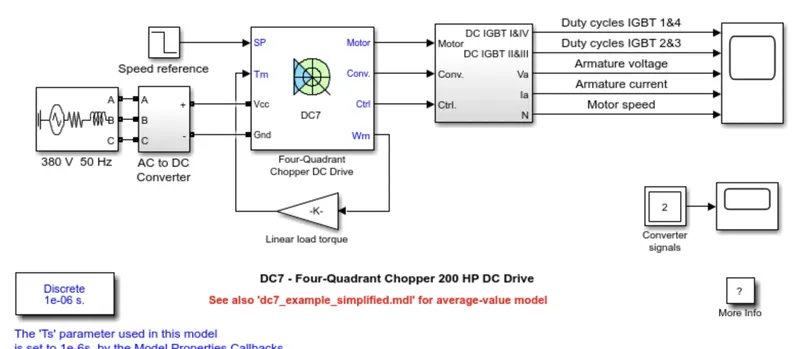
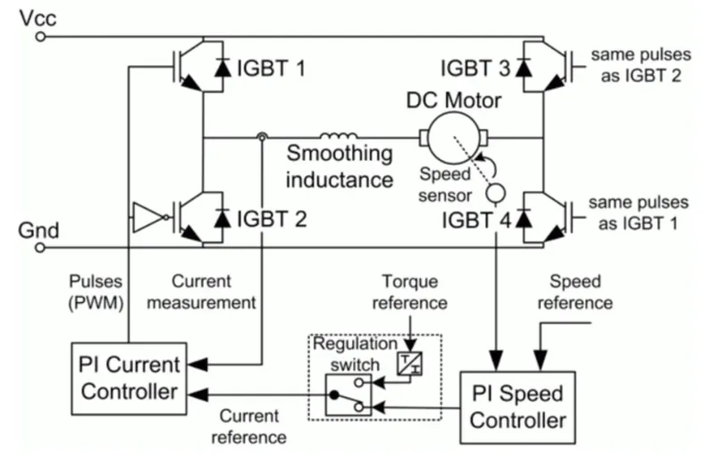
Control of speed is done by PI controller. The main difference between H BRIDGE and 4 QUADRANT DRIVE are
1) H bridge operates in forward motoring and reverse motoring, while DC7 Operates in four quadrant.
2) change in motor direction is dine by reversing of current direction in H bridge, where as in DC7 speed direction changes with the refernce speed.
2. Develop a 2-quadrant chopper using simulink & explain the working of the same with the relevant results. (Refer to article - Multiquadrant operation of motor )
ANS:2 QUADRANT CHOPPER: The Two-Quadrant Chopper block represents a two-quadrant controlled chopper for converting a fixed DC input to a variable DC output.The average voltage is always postive and average current may be positive or negative. It gives desired output depending upon the duty cycle given to it.
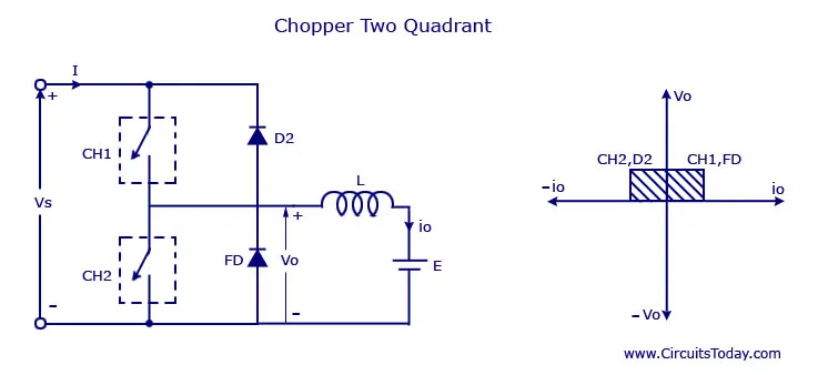
When ch1 is triggered on, the inductor stores the energy untill the dutycycle is on.The output across the load is vs. Here are the matlab model of 2 quandrant of dc motor.
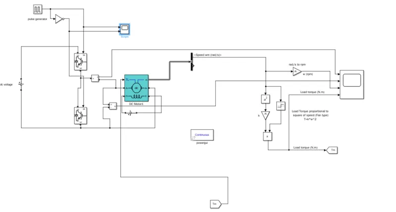
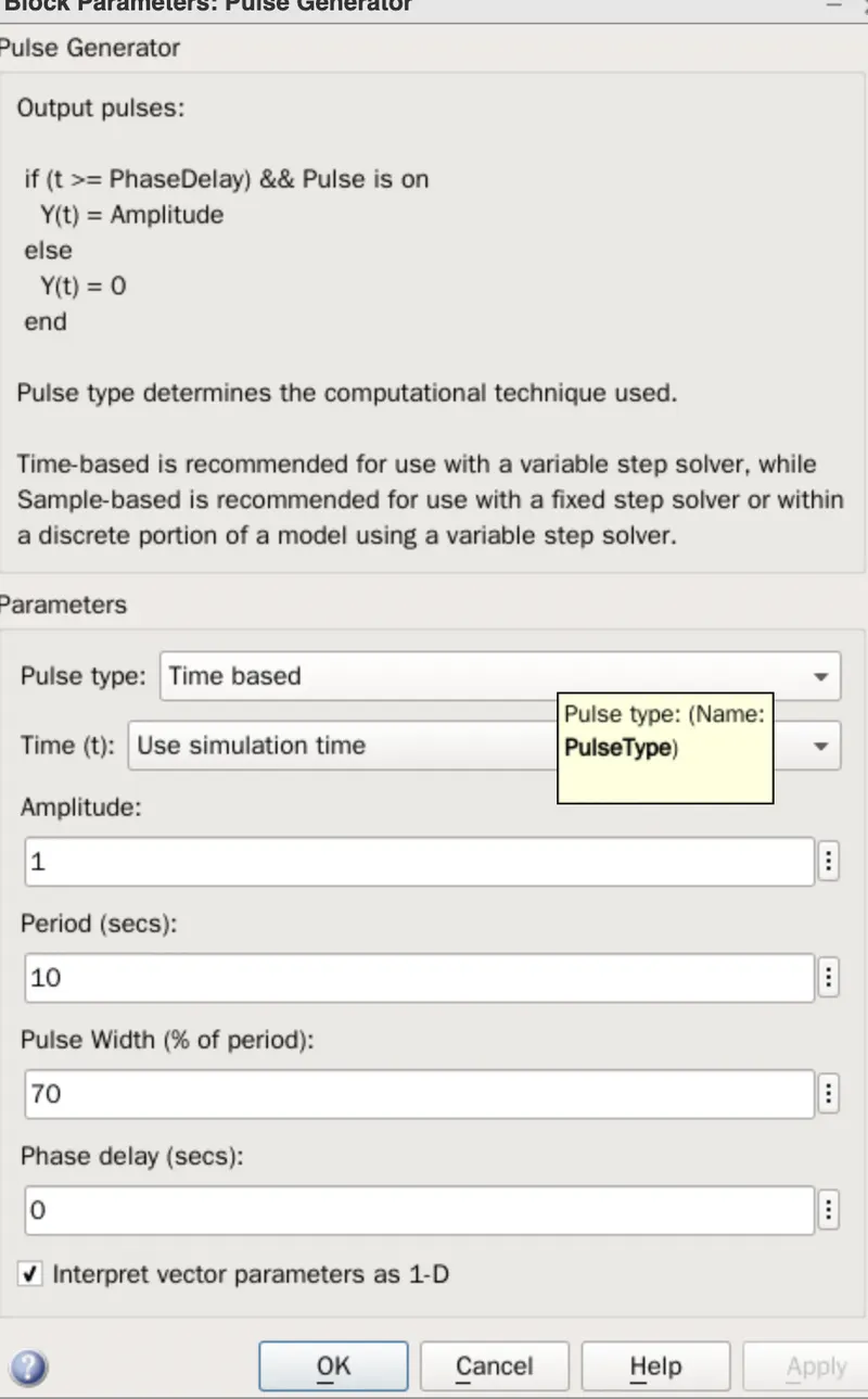
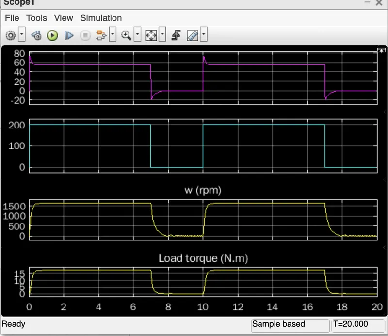
The pink graphs that current through the motor and blue line indicates voltage across the motor.So, by varying the duty cycle we can vary average voltage , speed and tprque.
3. Explain in a brief about operation of BLDC motor.
ANS: BLDC motor : Brushless dc motor is also called electronic commutated motor because the commutation is done by electronic circuit. They are also called permanent magnet dc motor. The construction of a brushless motor system is typically similar to a (PMSM), but can also be a induction motor.The advantage over brushless dc motors are less maintance, high speed due to no brushes, high efficient.
CONSTRUCTION: The construction is same as PMSM, where stator consists of permanent magnet and stator consists of 3 phases coil windings energinzed by dc currents. The coils are placed 120 degree partial displacement to produce torque in it. The stator windings are connected in delta. The rotor can consists of more number of poles. Higher the number is the smother the speed.
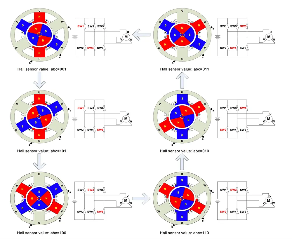 Each coil is wounded oppsite to create opposite poles to establish magentic poles. The back emf of the BLDC motor is trapizoidal in nature.
It is operated by six step commuation technique through inverter.
Hall sensors are used to find the rotor position so that the portion at which the rotor is energized. The disadvantages are high cost and speed control is complex.
APPLICATIONS:
- computer drives and computer cooler fans.
- electric vehicles, electric bicycles.
- modern fans.
- used in robots
- washing machines, pumps and dryers.
- Drones.