Week-6 Challenge: EV Drivetrain
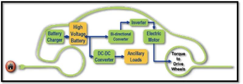
1. Which types of power converter circuits are employed in electric and hybrid electric vehicle?
ANS: The power converter circuits consists of semi conductors, capacitors and inductance and with proper duty cycle will gives desired outputs. They are majorally DC TO DC AND DC TO AC converters are used. DC to DC are used to lower or higher the battery voltage. The battery presents inside our EVs are mostly 200v because to increase storage in the car and voltage controllation is done by converters that are used into it. The classification is divided into 2 configurations 1) isolated and 2) non isolated converters.
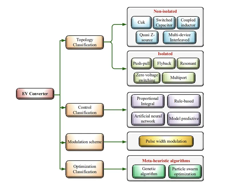
ISOLATED CONVERTERS: these types of converters are used for medium and high power conversion. They are used because of simple dc to dc converters due to high efficieny.Converters like cuk, coupled inductor and capactance etc are used.
NON ISOLATED CONVERTERS: They are used for low and medium power applications.Fly back and resonant converters are used.
INVERTERS: To drive the traction motor ac power is required. It is done by inverting dc to ac (3 phase) through inverters.
 ..
..
2. An Electric Vehicle's powertrain with 72V battery pack in shown in the diagram below. The duty ratio for acceleration operation is 'd1' and for the braking operation the duty ratio is 'd2'.
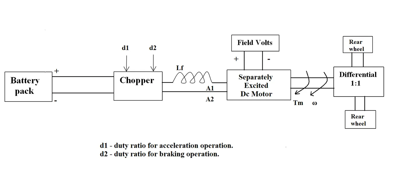
The other parameters of the electric vehicle is given below,
Motor and Controller Parameters:
Rated Armature voltage= 72 V
Rated armature current= 400 A
Ra= 0.5Ω, KΦ= 0.7 Volt second
Chopper Switching frequency= 400 Hz
The vehicle speed-torque characteristics are given by the below equation

What is EV steady state speed if duty cycle is 70%?
ANS:
Given that, battery voltage is 72 v then output after duty cycle of 70 percent is 0.7* 72 =50.4 v . Therefore the input voltage supplied to the motor is 50.4 v. Given values are rated values
We know that, V = IaRa + kΦw
T = IakΦ
solving both equations gives T = (v- wkΦ)* kΦ/Ra
T= (50.4- w *0.7)* 0.7/ 0.5
T = 70.56 - 0.98w ...........(1)
and from the given equation T = 24.7+ 0.0051w^2. ............(2)
From equations 1 and 2 to form a quadratic equation
0.0051 w^2 + 0.98w - 45.86 = 0
solving, w = 38.85 rad/se and -230.95 rad/se
speed cannot be in negative values, hence the speed at 70% duty cycle is 38.85 rad/sec.
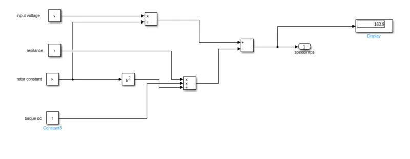
3. Develop a mathematical model of a DC Motor for the below equation using Simulink.
ω">ω= V/Kϕ">ϕ -Ra/Kϕ">ϕ^2 .T
ANS:
The equation can be modeled using simulimk. Here are steps to be processed.
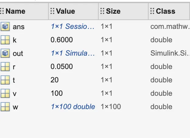
- Open matlab and create the script file in this format and run and save the workspace model.
- Open simulink and model the equations using blocks.
- Import the workspace values into the constant blocks and display the results in the outport.
% DC TORQUE VS SPEED %
v = input('input dc voltage='); % DC Input given to the motor%
r = input('armature resistane='); % ARMATURE resistance in ohm which is fixed%
k = 0.6;
 % ROTOR constant, k = k1* flux%
t = input('Torque');

4. Refer to the blog on below topic:
Induction Versus DC brushless motors by Wally Rippel, Tesla
Explain in brief about author’s perspective.
ANS:
Wally rippel is a long time developer and adovcate of battery electric vehicles written the blog about Induction vs DC brushless motors. He explains who the induction and Dc will rule over in upcoming electric era. He compares how the generation of techonology changes with time. Back in a day, lead acid batteries, Dc brush motors and contacters are used which takes more space and now they are replaced by lithium ion which are compact and dc brush motors are replaced by dc brushless and induction motors due to certain advantage and more efficient. Wally seeing that ruling of Dc brushless and induction motors for so many years.
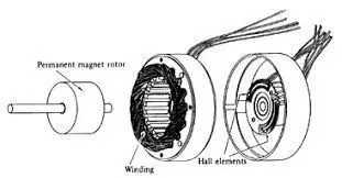
DC BRUSHLESS MOTORS: The construction is simple that rotor includes 2 or more permanet magnets and startoe is directly connected to inverter. This configuration of dc brushless gives more advanatge over brushed one. The motor controlling is done by inverter. With inverter brushless motor is no use. The controlling way of DC brushless is different than induction. They use position sensors. Less rotor heat is generated, due to no armature coils present in the rotor. so, cooling is easier and it is more efficient than induction motors.The DC brushless drive can also operate at unity power factor, whereas the best power factor for the induction drive is about 85 percent. This means that the peak point energy efficiency for a DC brushless drive will typically highWhen maximum torque is required, especially at low speeds, the magnetic field strength (B) should be maximum – so that inverter and motor currents are maintained at their lowest possible values. But changing the B field is not possible with permenant magnet.
INDUCTION MOTORS: The rotor includes armature coils in it. Both stator and rotor are arranged eith armature coils. It is a single excited machine that why it is operated in lagging power factor. This machine requires AC current(inverter is used). They are some few advatnages like starting torque ( requires less voltage for maximum torque). This advantage makes INDUCTION motors alive in the Ev industry. But motor controlling is done by v/f method which is conplex, beacuse of that reason they are moving to brushless motors. But still induction motors are widely used due to the low losses.
Wally concludes is that DC brushless drives will likely continue to dominate in the hybrid and coming plug-in hybrid markets, and that induction drives will likely maintain dominance for the high-performance pure electrics.