Week-7 Challenge: DC Motor Control
1A) Explain a MATLAB demo model named ‘Speed control of a DC motor using BJT H-bridge’.
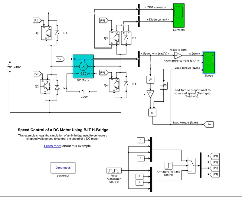
Explanation: The Bipolar Junction Transistor(BJT) when used for power switching applications, operates as IGBT. When it is conducting(saturated region), a forward voltage Vf is developed between collector and emitter. So IGBT block can be used to model the BJT devices.
The IGBT block does not simulate the gate current controlling the BJT. The switch is controlled by a simulink signal. The DC motor uses the present model(5HP 24V 1750rpm).
It simulates a fan type load (where Load torque is proportional to square of speed). The armature mean voltage can be varied from 0 to 240 V when the duty cycle (specified in the Pulse Generator block) is varied from 0 to 100%.
The H-bridge consists of four BJT/Diode pairs (BJT simulated by IGBT models). Two transistors are switched simultaneously: Q1 and Q4 or Q2 and Q3. When Q1 and Q4 are fired, a positive voltage is applied to the motor and diodes D2-D3 operate as free-wheeling diodes when Q1 and Q4 are switched off. When Q2 and Q3 are fired, a negative voltage is applied to the motor and diodes D1-D4 operate as free-wheeling diodes when Q2 and Q3 are switched off.
1B) Now let us see the results from the scope:
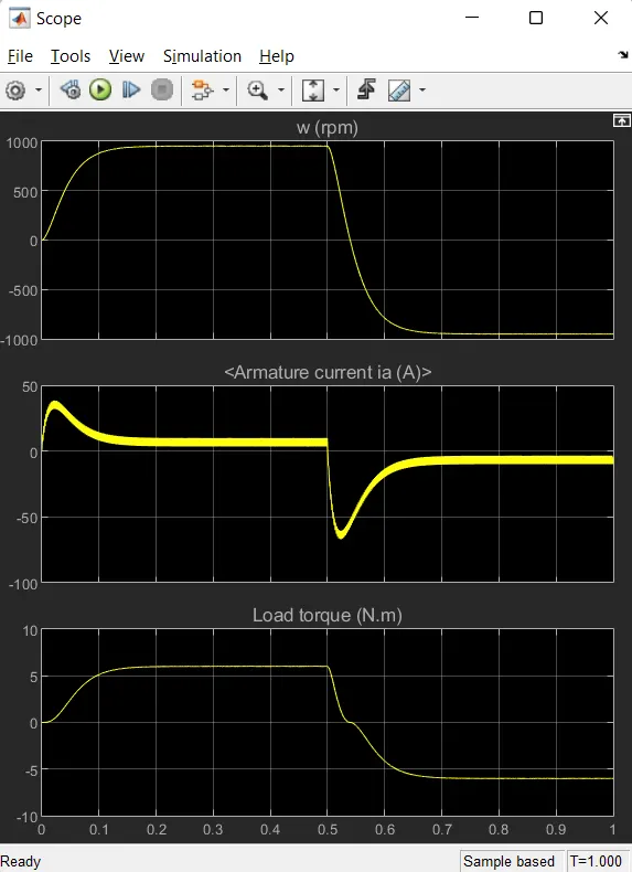
From the result we can observe that there is sudden increase in the armature current at the start. Armature current shoots up because there is no back EMF or counter EMF is zero initially. High torque is one of the DC motors main characteristics, hence to develop the torque high current is drawn.
lets us change the PWM value and check the result;
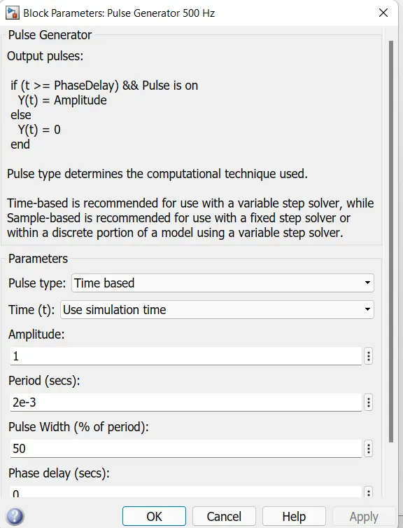
Pulse width is changed from 75 to 50%, means reduction in duty cycle ratio.
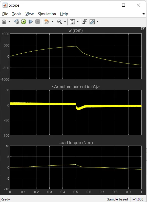
As we can observe, there is no shoot up of armature current in start. Hence it is clear that reduced duty cycle results in smooth variation of current.
1C) Refer to the help section of ‘The Four-Quadrant Chopper DC Drive (DC7) block’. Compare it with the H-bridge model.
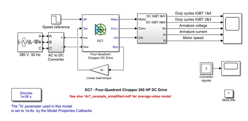
The 200 HP DC motor is separately excited with a constant 150 V DC field voltage source. The armature voltage is provided by an IGBT converter controlled by two PI regulators. The converter is fed by a 515 V DC bus obtained by rectification of a 380 V AC 50 Hz voltage source. In order to limit the DC bus voltage during dynamic braking mode, a braking chopper has been added between the diode rectifier and the DC7 block.
The first regulator is a speed regulator, followed by a current regulator. The speed regulator outputs the armature current reference (in p.u.) used by the current controller in order to obtain the electromagnetic torque needed to reach the desired speed. The current regulator controls the armature current by computing the appropriate duty ratios of the 5 kHz pulses of the four IGBT devices (Pulse Width Modulation). For proper system behaviour, the instantaneous pulse values of IGBT devices 1 and 4 are opposite to those of IGBT devices 2 and 3. This generates the average armature voltage needed to obtain the desired armature current. In order to limit the amplitude of the current oscillations, a smoothing inductance is placed in series with the armature circuit.
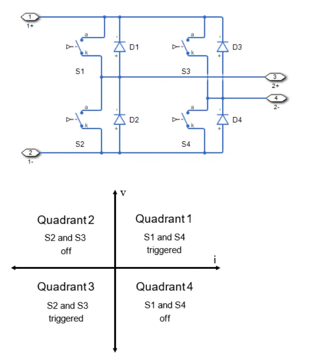
The 4 quadrant chopper DC drive is operated in 4 different modes i.e Forward motoring, Forward Braking, Reverse Motoring and Reverse Braking. Regenerative braking is achieved due to the back EMF. Each quadrant describes the different operation of the machine.
H-bridge Model:
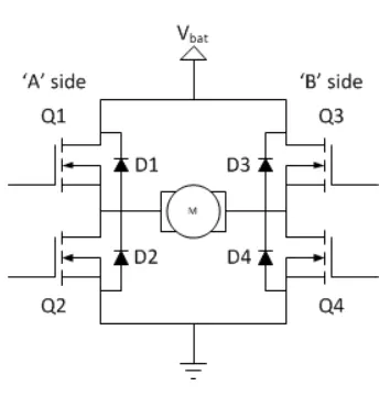
H-bridge is a circuit with 4 switching element and a load in middle, in H-like connection. The switching element Q1,Q2,Q3,Q4 are bipolar transistors, and IGBT's in some high-voltage application. The diodes D1,D2,D3,D4 provide path for current flow when the motor is switched on. The top end of the ciruit is connected to a power supply and the bottom end is grounded.
Operation: When Q1 and Q4 are turned on the left part of the ciruit gets connected to the power supply and the right part is gorunded. The current starts flowing from Q1 to load, flows to Q2 and finally to gorund in forward direction. And this is known as Forward motoring.
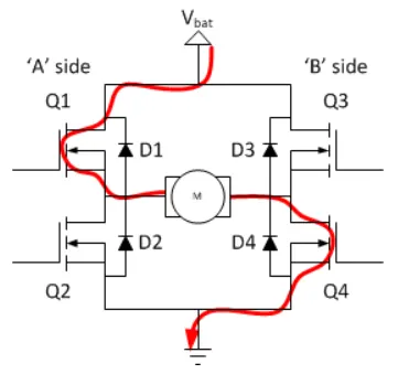
If the motor has to be engergized, and current flow should not be stopped, then the other side i.e Q2 and Q3 are turned on. By doing so the current flows in reverse direction and the motor starts spinnig in reverse direction. These are only two methods to operate the H-bridge circuit.
We should remember, the switches Q1&Q2 and Q3&Q4 should not be turned on at a same time. If it is done so then the ciruit gets destryod due to the short circuit. This conidition is called as 'shoot-through' condition.
| Four-Quadrant Chopper DC Drive | H-Bridge Model |
|
The motor can be operated in 4 different modes. (Forward Motoring, Reverse Motoring, Forward Breaking, Reverse Braking) |
Here only two modes of operation is possible. (Forward Motoring and Reverse Motoring) |
| Regenerative braking can be acheived. | Regenerative braking is not possible. |
| Discrete signal is given to the 4 quadrants. | Continuous signal is given. |
| 4 quadrant chopper is used in automobile applications for the control of DC motor speed and direction. | Used in robotics and electro-mechanical devices to control the speed and direction of the DC motor. |
2) Develop a 2-quadrant chopper using simulink & explain the working of the same with the relevant results.
Working of a 2-quadrant chopper:
In this type of Chopper, average voltage will always be positive but the output current will be positive and negative. Let us look at the ciruit.
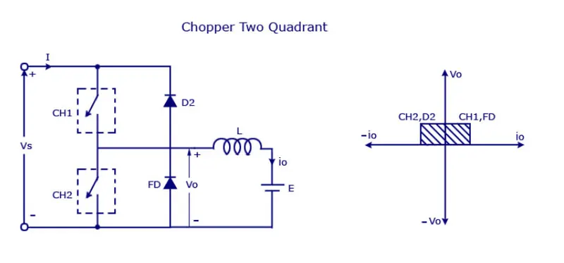
The two switches seen in the ciruit should not be turned ON simultaneously, which may lead to the short ciruit in lines. For motoring and regenerative braking these type of chopper configuration is used.
We wil always get the postive voltage as the freewheeling diode is present across the load. When CH1 is turned ON the current flows to the load and inductor stores energy. When chopper is ON, freewheel diode conducts and the output voltage Vo is equal to source voltage Vs. When CH1 is OFF, the current flows in reverde direction, current io flows to the source voltage through diode D1 when CH2 is turned ON.
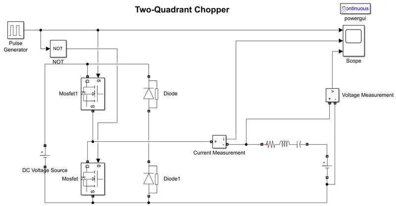
Construcion:
- Two MOSFET blocks and Diode blocks are connected with a DC voltage source as shown.
- Pulse Generator is used for the pulse input to the MOSFET, a NOT gate is also used to avoid the closing of both the gates at a same time.
- Using NOT gate switching of MOSFET is controlled, when one MOSFET is ON the other will be turned of and vice versa.
- A DC voltage source is connected in series with load.
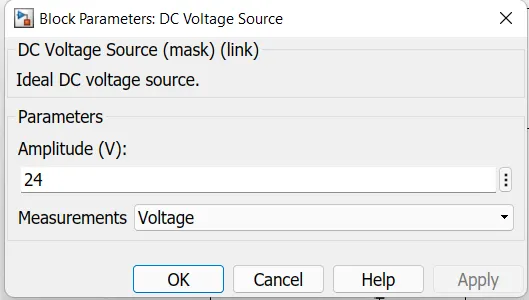
DC voltage source for the supply.
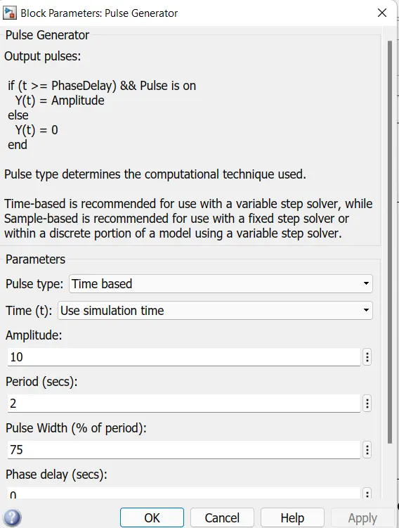
The amplitude of Pulse generator is kept at 10 and the period of 2secs is maintained for a clear view of result.
Pulse width is maintained at 75%.
Result:
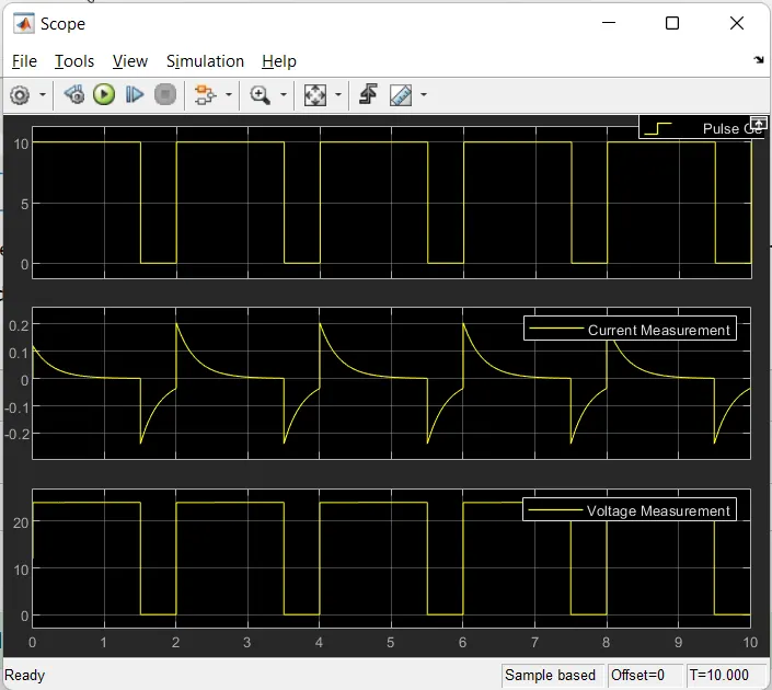
It is clear from result, the 2-quadrant DC chopper will always have positive voltage but output current is positive and negative.
3) Explain in a brief about operation of BLDC motor.
A Brushless DC motor is a Permanent Magnet synchronous motor which is driven by Direct current and achieves the electronically controlled commutator system instead of mechanical commutation system. In this motor permanent magnet rotates and the current carrying conductors are fixed.
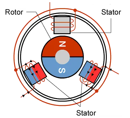
Construction: The permanent magnets are attached to the rotor and the current carrying conductors are located on stator. Stator of a BLDC motor made up of stacked steel laminations to carry the windings. These windings are placed in slots which are axially cut along the inner periphery of the stator.
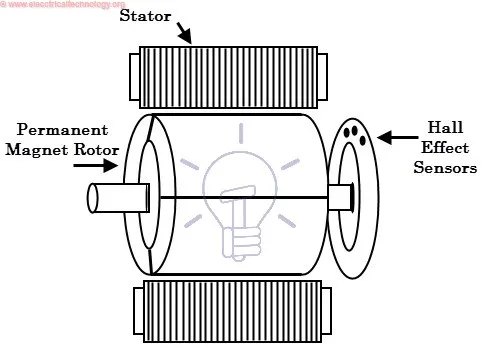
The main design difference between a BLDC and Brushed motors is the repalcement of mechanical commutator with an electric switch circuit.
Working Principle: BLDC works on the principle of conventional DC motor i.e the Lorentz force law which states that whenever a current carrying conductor is placed in a magnetic field it experiences a force. In this motor permanent magnet rotates and the current carrying conductors are stationary. BLDC is essentialy flipped insdie out, eliminating the need of brushes to push the magnetic field.
Advantages over brushed DC motor:
- Due to the use of permanent magnet it has efficiency 85%-90%, where in brushed DC motor has an efficiency of 75%-85%.
- No mechanical commutator and associated problems.