Week -2
1)
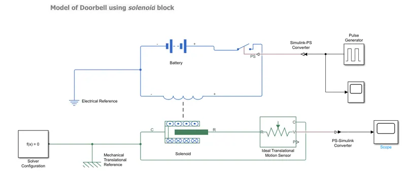
The above model is created to show the operation of the switch and the transition output.
Parameters used:
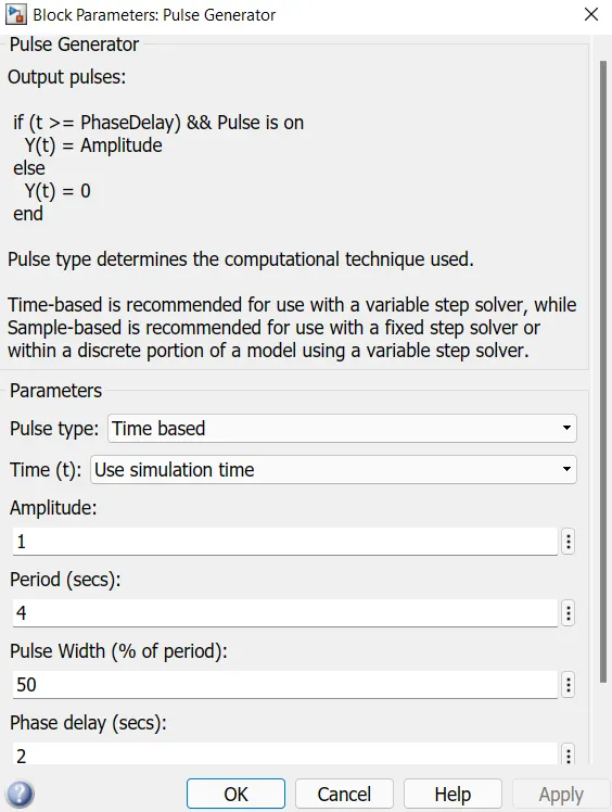
a) Pulse Generator: Used to provide the input signal for the operation of switch and to create the square wave pulse. As the given challenge is to make the switch to be closed for 2sec and then released, below parameters are assumed.
b) Switch block: allows the flow of current when the circuit is closed loop and is controlled by the external physical signal. If the external physical signal is greater than the threshold value(i.e 0.5) then the switch is closed , otherwise the switch is open.
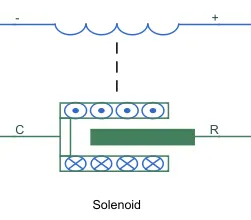
c) Solenoid: used is an elctromagnetic device that creates a flux when electric current flows through it.
d) Battery: used for electrical supply with positive and negative terminals to complete the electric circuit.
e) Ideal Translational Motion Sensor: used to measure the velocity or displacement in a mechanical translation network. Here used to understand the movement of plunger.
f) Simulink-PS converter & PS-Simulink converter: used to convert the Simulink input signal to a Physical Signal and Vice-Versa.
g) Electrical and Mechanical Reference: used for Electrical grounding and mechanical ground frame.
h) Solver Configuraton: block that acts as complete equation and used to generate the output.
i) Scope: Gives the plot of the outputs.
The simulation was run for 10seconds and the result obtained is as shown below.
Results:
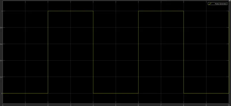
The above plot represents the pulse generated for which the phase delay given is 2 seconds to open and close the switch. when the switch is closed the power flows through the circuit to solenoid connected and the armature(plunger) moves inward and thus the bell operates.
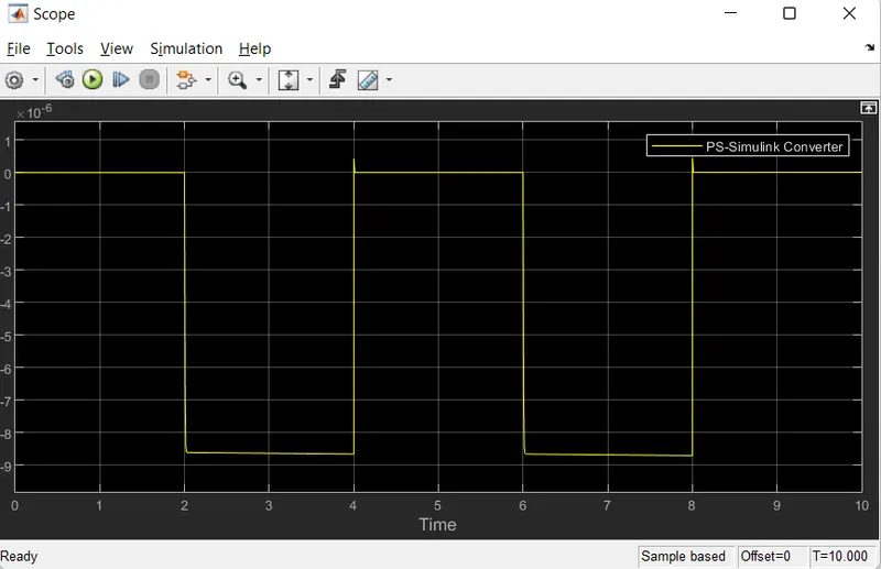
The above plot is the observation of the physical movement of the pulnger.
2) Use a thermistor to sense the temperature of a heater & turn on or turn off the fan as per the below conditions:
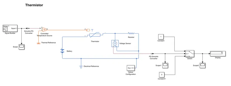
The above Simulink Block System consists of following Simulink and Simscape block system
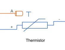
Thermistor: It is a type of resistor whose resistance varies with the change in temperature and so is used to measure temperature. Here resistance of the thermistor increases or decreases w.r.t temperature. The output of the thermistor is in the form of voltage or current and so the increase in voltage/current indicates the increase in temperature.
Given inputs :
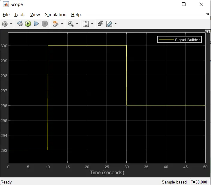
Temperature source: 20 °C from 0 to 10 seconds, 27 °C from 10 to 30 seconds, 23 °C from 30 to 50 seconds
Fan conditions: ON if the temperature above 25 °C, OFF otherwise
to provide the input as per the given input Signal Builder block is used,
Signal Builder: 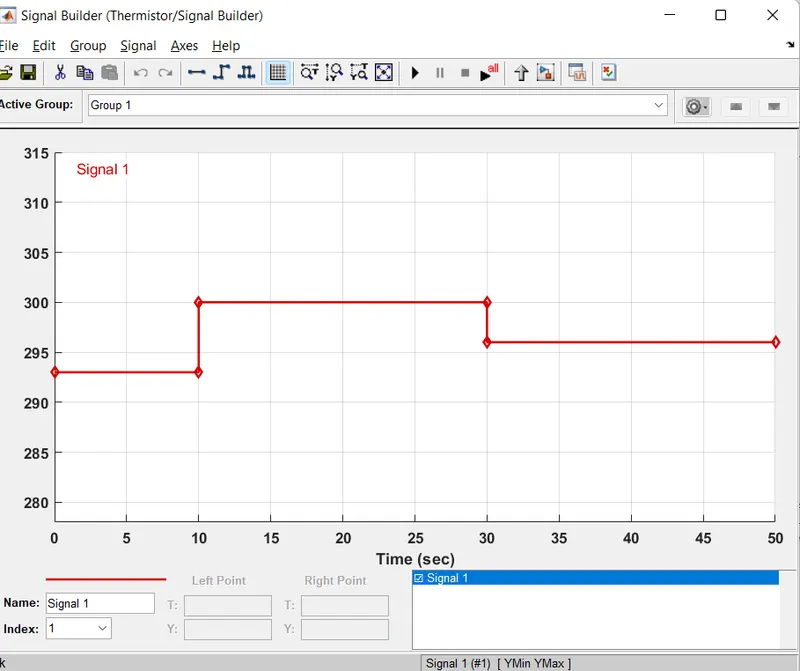
here the temperature is converted into Kelvin and hence 20°C=293K, 23°C=296K and 27°C=300K
Controlled Temperature Source(CTS):
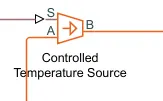 This block represents an ideal energy source in a thermal network that can maintain a controlled temperature difference regardless of the heat flow rate. The temperature difference is set by the physical signal port S. A positive temperature difference causes the temperature at port B to be greater than the temperature at port A.
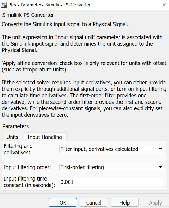
Simulink-PS Converter: This block is used to convert the Simulink signal into Physical signal. The output of the signal builder is provided as the input to the CTS at the port S using the Simulink-PS Converter.
Note; Integrated input is provided in the Simulink-PS Converter which makes the solver read the system.
Battery: Used to provide the source to the Simulink block which represents the dc or ac.
Resistor: A linear resistor is used to control the amount of current flow from the battery

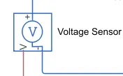
Volatge sensor: a device that converts voltage measured between any electrical connections into a physical signal proportional to the voltage
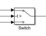
Switch: used for ON and OFF control as per the given input.
Input given from the Signal Builder as per the given conditions
Output from Scope1
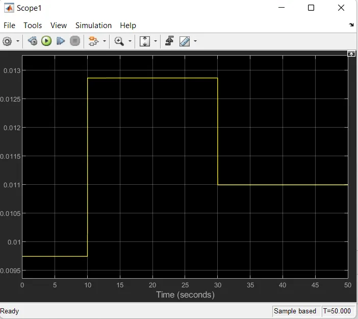
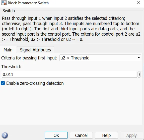
from the above plot it is clear that the Fan is in ON condition when the threshold(voltage value) is above 0.011 i.e 296K and Fan is off when the value is below the threshold.
Switch threshold
Output scope2
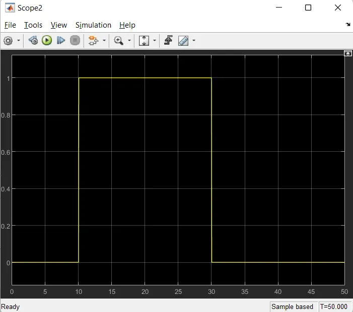
For 0 to 10sec fan is in OFF condition as the value is below the threshold.
For 10 to 30sec fan is ON condition as the value is above the threshold.
For 30 to 50sec again the fan is in OFF condition as the value is beow the threshold.
Hence from above plot the given conditon is satisfied, Fan remains in ON condition when the value is above the threshold 0.011(i.e 298K or 25°C)