Week - 4
1) Control logic of Washing Machine using Stateflow
Let us first understand the working procedure of the Washing machine;
Washing Machine used as clothes washer is Electrically controlled which includes the drum inside, motor, pump, inlet an outlet valves. It handles a various tasks like soaking, washing, rinsing and drying in a short period of time. One will set a program as per the requirement and switch on the power supply. The program runs in different stages as mentioned earlier based on a control logic. Lets create the control logic in the Simulink, to do that we have to follow the below steps.
- Insert the chart in the simulink and create the logic system using the stateflow.
- Provide the "if" cnditions as per given at respective stages
- Soaking time should be 200s followed by Washing time of 100s.
- Then rinsing happens for next 20s & dryer runs for 50s
- To ON the washing maching input power supply needs to be applied and condition is given to flow to the next operation.
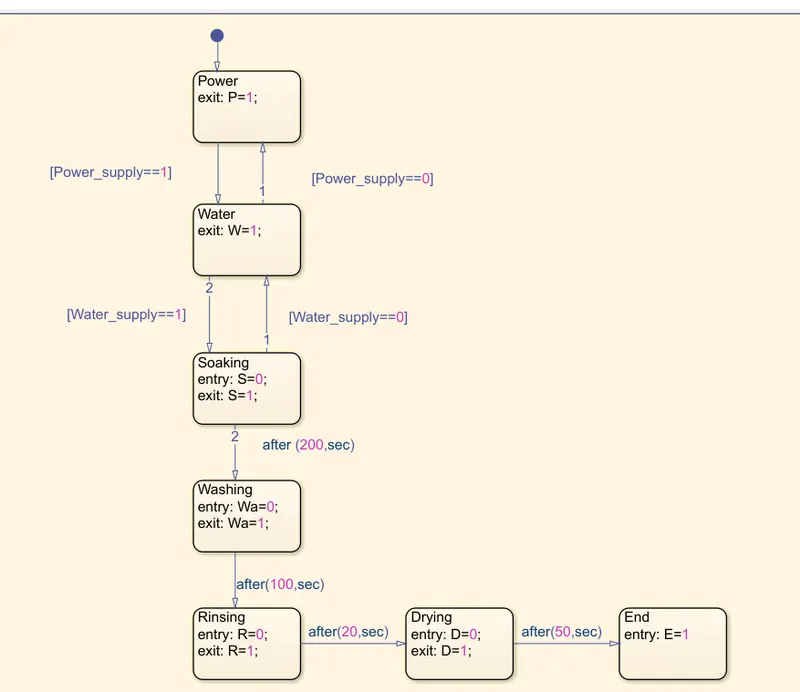
- Once the power supply is given water supply is given to the perform the operation. here the condition is given as entry=0 and exit=1 i.e if the conditon is not satisfied the process stops and comes back to the previous state.
- The same process is applied for each stateflow with the time of working in seconds as given.
- The stateflow of the washing machine is created as shown below.
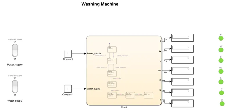
- Now input and output ports are added, for the input to the stateflow is given through the constant block to give the input value.
- Rocker switch is used from the library for the power supply and water supply and is connected to the constants for ON and OFF operation.
- Display blocks are connected to each outputs for the dispaly of the results of operation.
- Lamp block is used at each stages to indicate the 'ON' or 'OFF' operation at the particular stage.
Simulink model created is as shown below
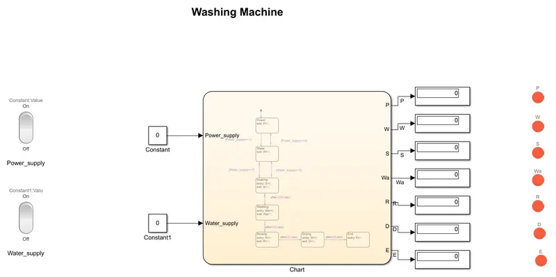
- The power supply switch is in 'OFF' condition and so the constant block value is 0 which results zero in output value of all operations.
- Lamp blocks displays Red color as the output is zero.
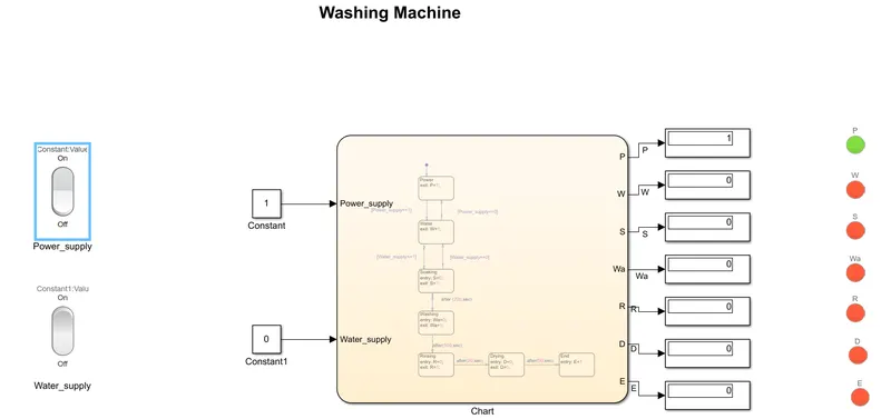
- Now the power supply switch is turned 'ON' and the constant block connected with the switch dispalys the value 1, resulting the output of the power displays the value 1.
- Lamp block connected to the power dispaly is turned green as the output condition is satisfied.
- Water supply switch is in 'OFF' condition which means there is no water flow into the machine so as per the given condition the value results in 0 and the process stops indicating the Red lamp.
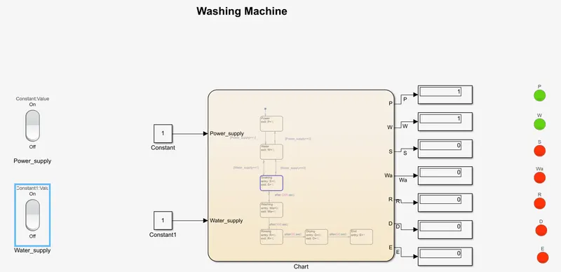
- Now both power supply and water supply switchs are in 'ON' conditon. Power is given from the input and the operation starts, water supply is also given initiating the value 1.
- Lamp of both the output is Green indicating the start of the process.
- Once the condition of the water supply is satisfied, the operation proceeds for next stage in the state flow.
- Each operations are runned as per the time duration given in the state flow and the results are obatined in dispalye blocks.
- Lamps as a result indicates green color at each stage. Once the complete operation is finished, display E indicates the value and the Lamp indicates green color.
2) Gear shift logic
Shifting of gears means going from one gear to another gear using the gear lever/slider. If speed is reduced then gear is downshifted and upshifting means going to the higher gear with increase in speed.
given data;
Speed Range(kmph) Gear
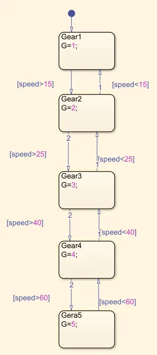
0 to 15 1
16 to 25 2
26 to 40 3
41 to 60 4
Above 61 5
State flow of the gear shift logic is as shown below
Simulink model of the gear shift logic is as shown below
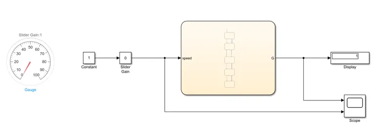
Blocks used fo the model:
- Stateflow/Chart- control logic of the gear shifting.
- Slider gain- used as throttle to vary the speed.
- Constant- used to multiply the input.
- Gauge- used as a speedometer to show the speed of the vehicle.
- Display- used to show the gear position.
- Scope- to plot the grap of speed vs gear.
Process
- As we can see in the model slider is at 0 hence 1 is displayed as first gear.
- As per the given sequence the range of the first gear is 0-15kmph.
- As the speed is increased stateflow checks the condition of the input speed and displays the gear position.
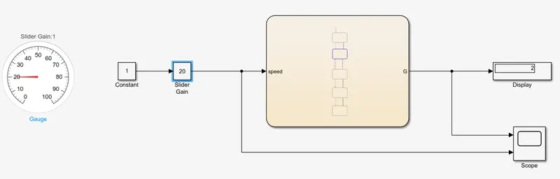
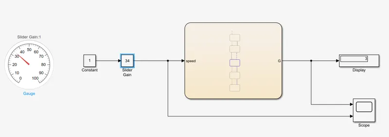
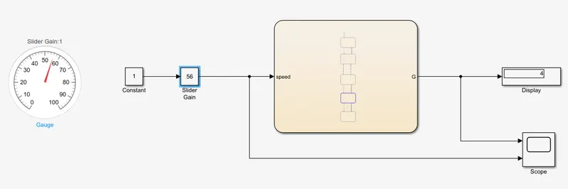
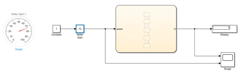
- Gear changes takes place as per the given range of speed(kmph) as shown below.
Gear 1
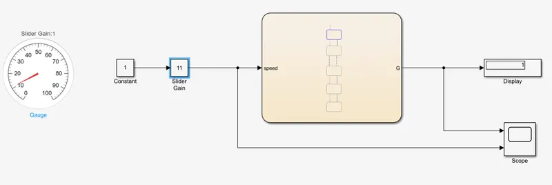
Gear 2
Gear 3
Gear 4
Gear 5
Output-
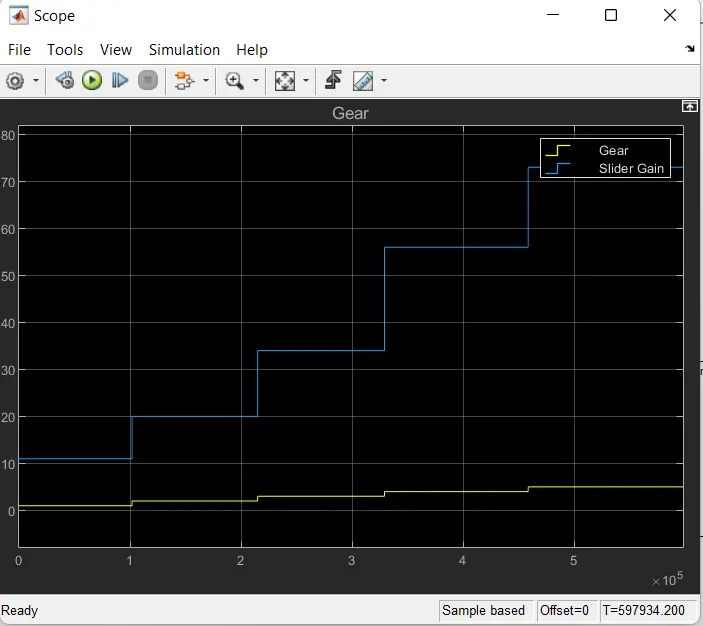
From the output observed in scope it is clear that the gear shifting takes place as per the given speed range(input).