Week-7 Challenge: DC Motor Control
1.
Answer:
This example shows the simulation of an H-bridge used to generate a chopped voltage and to control the speed of a DC motor.
MATLAB Simulink model of ‘Speed control of a DC motor using BJT H-bridge’:
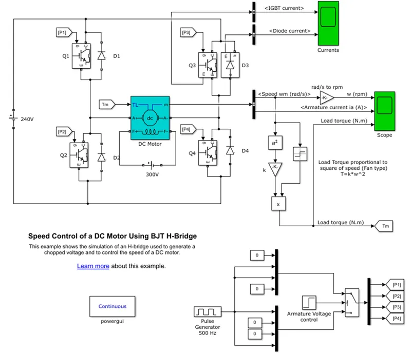
- The DC voltage of amplitude 240 V is applied to the H-bridge converter.
- The H-bridge converter consists of four BJT/diode pair.
- The BJT model is simulated by the IGBT block.
- The DC motor of 5 HP 240 V 1750 RPM rating is used as a load.
- The DC motor is a fan type of load in which load torque is proportional to square of speed.
- The armature voltage can vary from 0 - 240 V when the duty cycle is vary from 0 - 100 %.
- The pulse generator is used to give the controlled signals to the switches (1/0).
- The DC motor field is excited by the separate DC voltage of 300 V.
- The operation is two quadrant operation in which transistors are switched simultaneously as Q1 and Q4 or Q2 and Q3.
- When Q1 and Q4 are fired, the positive voltage is applied to the motor
- When Q2 and Q3 are fired, the negative voltage is applied to the motor.
- At the starting, positive voltage is applied to the motor and motor starts in the positive direction
- The duty cycle is 75 % that means the DC voltage applied to the motor is 180 V.
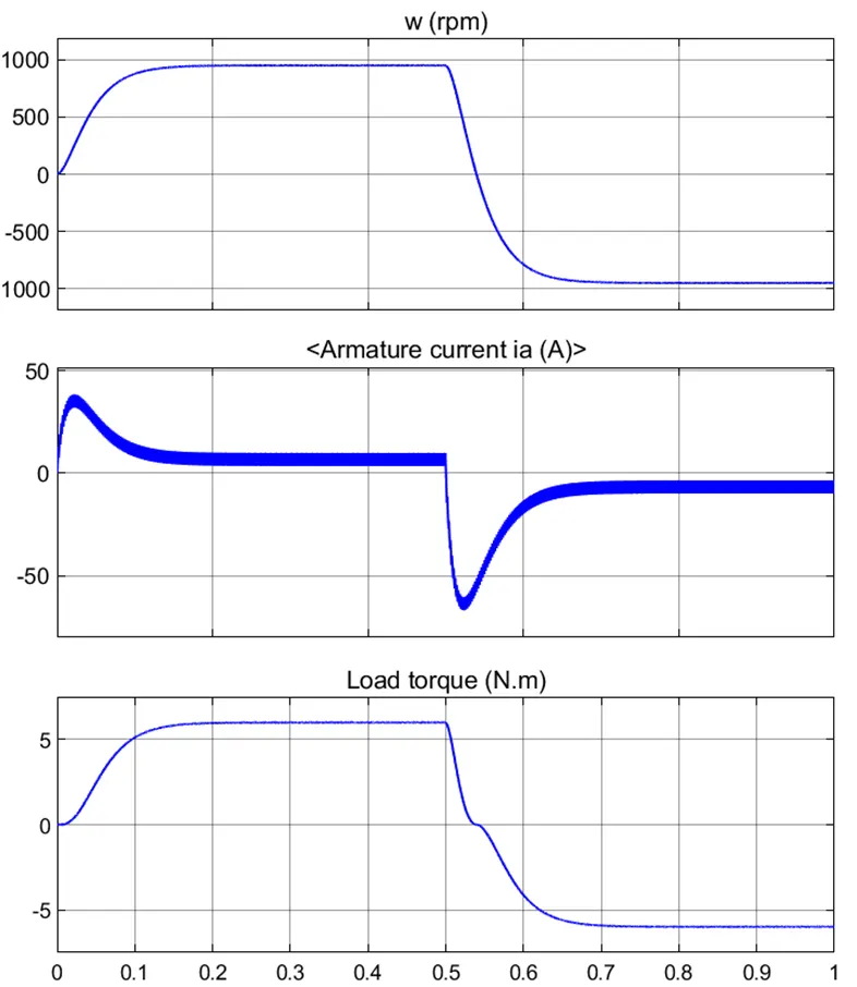
- In the above figure, the speed starts increasing and attains steady state condition.
- After 0.5 sec, the speed becomes negative and motor operate in negative direction.
- In the armature current graph, there is a transient at the beginning due to the switching operation of switches Q1 & Q4 and then current attains the steady state condition upto 0.5 sec.
- After 0.5 sec, negative voltage is applied to the switches and motor operate in negative direction.
- At 0.5 sec, there is spikes due to the switching operation of the switches Q2 and Q3.
- The load torque waveform follows the speed as the torque is proportional to the square of the speed.
B.
This example shows the DC7 four-quadrant chopper DC drive during speed regulation.
MATLAB Simulink model of ‘The Four-Quadrant Chopper DC drive (DC7) block’:
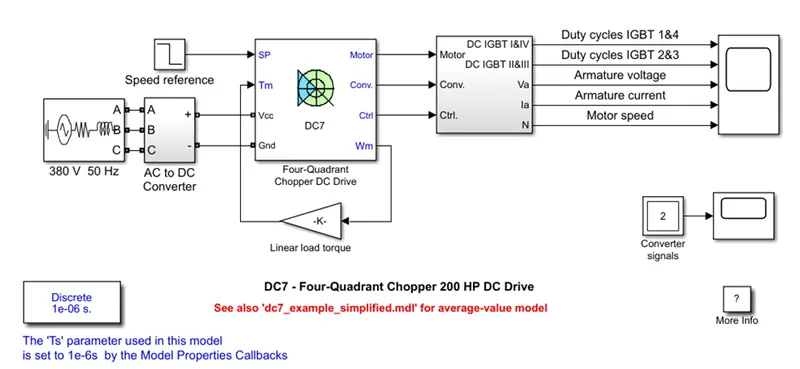
- In the above model, the DC voltage source of 380 V 50 Hz is used and connected to AC to DC converter.
- The 200 HP motor is used and its field is excited by the separate DC voltage source of 150 V.
- The IGBT converter is used to give armature voltage which is controlled by two PI controller.
- The input 380 V is rectified to the 515 V DC and is given to the IGBT converter.
- In the AC to DC converter subsystem, a braking chopper is added to limit the DC bus voltage during dynamic condition..
- The speed regulator is used to give the reference armature current in order to obtain the electromagnetic torque neede to reach desire speed.
- The current regulator is used to control armature current by computing the appropriate duty ratios of the IGBT devices.
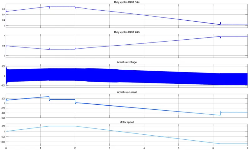
- The reference speed is set to 500 RPM at t=0 sec, so in the above graph speed is increasing and reaches steady state at t=1.3 sec.
- The switching operation is very fast and small ripple is observed as compare to the H-bridge.
- The armature current starts decreasing after t=2 sec that causes the motor to decelerate and run in the negative direction.
2. Two quadrant chopper
In this chopper average voltage is always positive and the avarage current may be positive or negative. The two switches CH1 and CH2 should not be turned ON simultaneously as this may cause short circuit in the supply lines. This chopper configuration is used for regenerative braking and motoring. We will always get the positive output voltage as the freewheeling diode is present across the load. When chopper CH1 is ON the current flows from source to load. The inductor stores energy. When CH1 is turned OFF the freewheeling diode starts conducting and the output voltage will be equal to input voltage. The direction of load current will be reversed. The current will be flowing towards the source. The load current will be negative when CH2 is ON. The current completes its path to the diode D2.
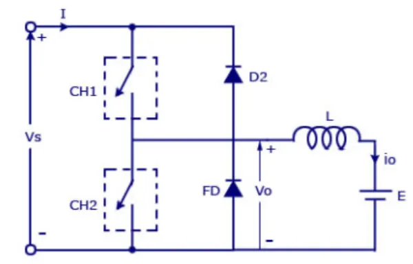
Simulink Model of two quadrant chopper:
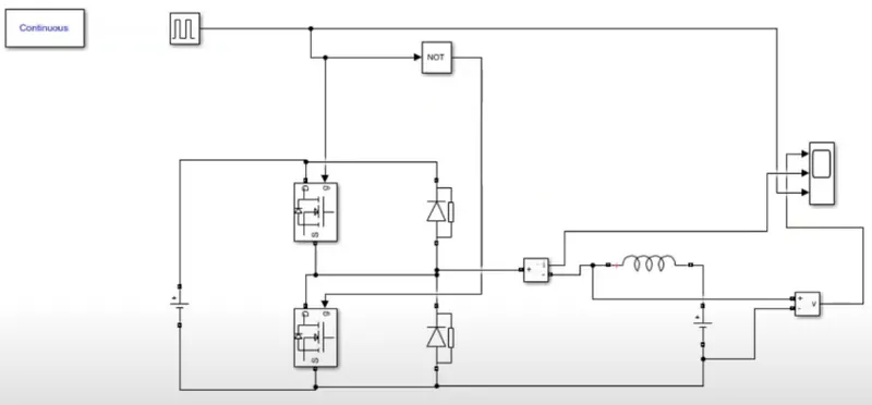
Result:
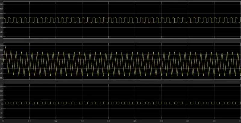
- The first waveform is of average output voltage, it is seen that the voltage is positive throughout the simulation.
- The input voltage is given as 24 V and we get the same amplitude of 24 V in the output.
- The second waveform shows the average output current.
3.
Operation of BLDC motor:
BLDC motor works on the principle similar to that of a conventional DC motor, i.e., the Lorentz force law which states that whenever a current carrying conductor placed in a magnetic field it experiences a force. As a consequence of reaction force, the magnet will experience an equal and opposite force. In case BLDC motor, the current carrying conductor is stationary while the permanent magnet moves.
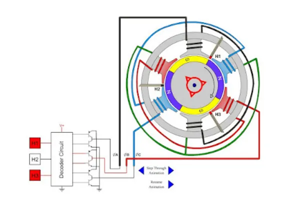
When the stator coils are electrically switched by a supply source, it becomes electromagnet and starts producing the uniform field in the air gap. Though the source of supply is DC, switching makes to generate an AC voltage waveform with trapezoidal shape. Due to the force of interaction between electromagnet stator and permanent magnet rotor, the rotor continues to rotate.
Consider the figure below in which motor stator is excited based on different switching states. With the switching of windings as High and Low signals, corresponding winding energized as North and South poles. The permanent magnet rotor with North and South poles align with stator poles causing motor to rotate.
Observe that motor produces torque because of the development of attraction forces (when North-South or South-North alignment) and repulsion forces (when North-North or South-South alignment). By this way motor moves in a clockwise direction.
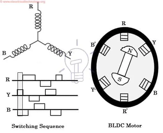
Here, one might get a question that how we know which stator coil should be energized and when to do. This is because; the motor continuous rotation depends on the switching sequence around the coils. As discussed above that Hall sensors give shaft position feedback to the electronic controller unit.
Based on this signal from sensor, the controller decides particular coils to energize. Hall-effect sensors generate Low and High level signals whenever rotor poles pass near to it. These signals determine the position of the shaft.