Week - 4
#4
1. Implement control logic of a "washing machine" using Stateflow as per given sequence:
- If the power supply is available, the system gets activated.
- If the Water supply is not available, stop the process & indicate through LED.
- Soaking time should be 200s followed by Washing time of 100s.
- Then rinsing happens for next 20s & dryer runs for 50s.
After all the processes have completed turn on the finished LED.
Answer:
Simulink model for the control logic of washing machine using stateflow is given below:
Simulink Model:
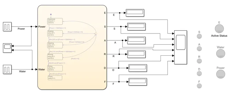
- As per the system requirement, the simulink model shows the complete process of washing of the cloths which represents the different states as soaking, washing, rinsing and drying.
- As per the above simulink model, pulse generator blocks are used to give the power supply and water supply to the washing machine. As we have to give the continuous power and water supply to the machine so in case any of them cuts off, the system should get deactivated. The lamp is used to show the active status of the machine. The separate two lamps are also used to show the shortage of water and power.
- The pink color block represents the stateflow for the machine which uses the control logic for processes like soaking, washing, rinsing and drying.
- The display blocks represent the status of the each process in the washing machine If the particular process is active it will display the status as 1 that means that process is in action. If the status is 0 that means this process is inactive. Accordingly the lamps are also used to show the active status of the each process.
- The scope block is used here to show the time period of the each process in the washing machine and the status of water and power supply.
Stateflow:
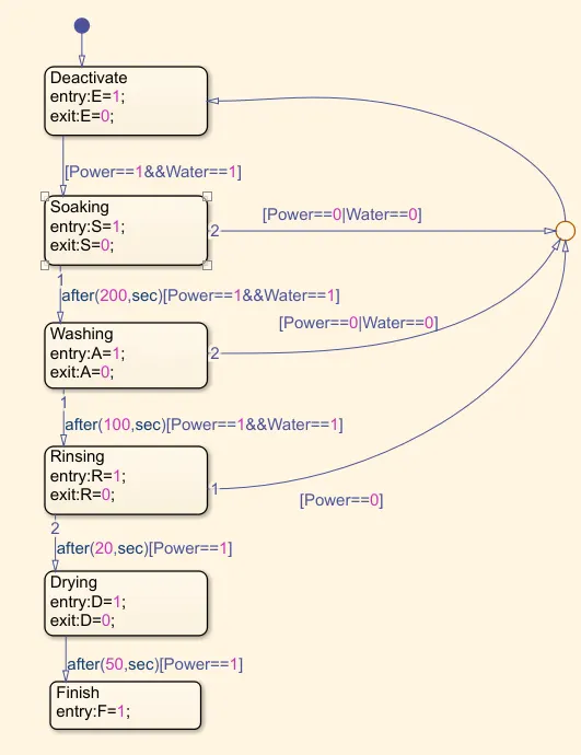
- The figure above is the stateflow chart of the washing machine that contains control logic for various states of the machine and transition event.
- As we have to check the status of the machine through out the working, so we took the first state as deactive state. To check either it is active or deactive. This state shows that initially machine is OFF/deactive. We enter the logic 1 here which represents the machine is OFF initially. Now power and water supply is given and at exit there is logic 0 that represents the machine is ON so we can carry out further processes.
- As there is a transition from one state to another, so condition here is to check both the input i.e. water and power supply are 1 or not. We use the AND operation to fulfill both the conditions. If both the conditions are true then the further process is initiated.
- This all states represents the logic as entry and exit. While entering in the state the logic is 1/ON that is the state is active and at exit the logic is 0/OFF means the state is deactive.
- The soaking process is initiated which represented by the logic S=1 and and it is active for 200 sec. The logic S=0 shows that the soaking process runs for 200 sec.
- At each state we must check for our necessary condition of feeding water and power to make sure that the machine will not turn OFF.
- The washing process continues for 100 sec as per the logic given in the stateflow and the rinsing process is active for 20 sec.
- At transition from rinsing to drying, only logic for power is given as 1/ON because water is not require for further states.
- The drying process is active and it finish after 50 sec that represented by the finish state. The finish state shows the logic of 1 means all the processes are finished and then the lamp will glow to indicate it.
- In case of power shortage or water supply is not available, the system must deactivate. This condition is shown by the OR operation. For this condition a junction is used to turn OFF the process. Then the lamp will show the deactivated status.
If the power supply is available, the system gets activated:
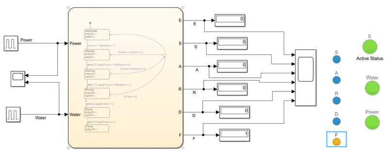
- In the above model, continuous power supply and water supply is available.
- After the simulation is completed, the LED shows the status of all the processes.
- Tha five blue LEDs show the status of all the processes like soaking, washing, rinsing and drying state and it indicate that all the processes are finish.
- The yellow LED is turn ON which shows the finish status after completion of all the processes.
- Tha green colour LEDs shows the continuous water and power supply to the system.
- The LED named as active status is turn ON (Green in colour) as it represents that the system is active.
- The below graph shows the time period of each state in the system.
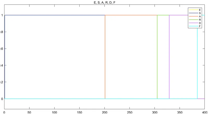
- The above graph represents the time period for each process.
- It shows the soaking time is 200 sec, washing time is 100 sec, rinsing time is 20 sec and drying time is 50 sec.
- After that finish status is turn ON.
If the power supply is not available, the system gets deactivated:
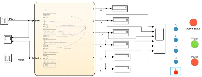
- From the above simulink diagram, it is seen that the power is interrupted and it is indicated by the red colour LED.
- There is continuous water supply and it is shown by the green colour LED.
- The LED named active status is indicating red colour as the system is deactivated.
- The LED named 'F' shows the finish status which is red in colour means all the processes are stop.
- Below graph shows the interrupted power supply and continuous water supply.
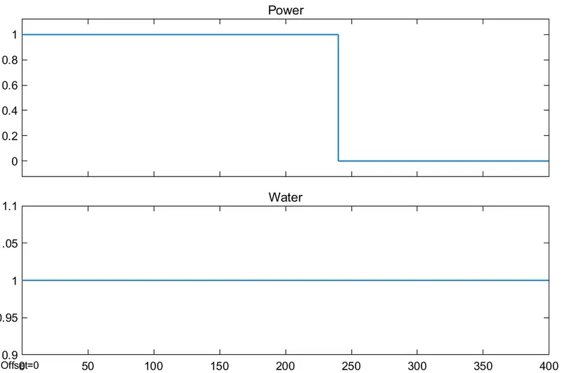
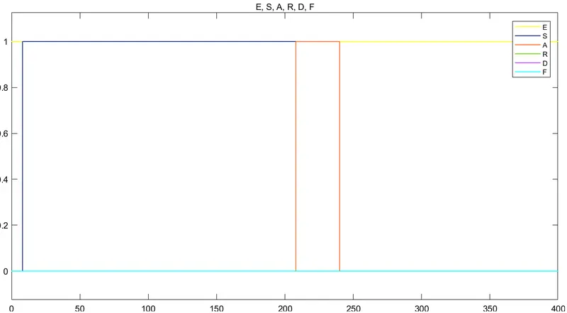
- From the above graph it is seen that the soaking process is active for 200 sec and washing process stop as soon as the power supply is interrupetd.
- The graph shows that after washing further processes are not activated.
- The yellow colour line indicate logic 1 which means the system is deactivated as the logic 1 shows the deactive status.
If the water supply is not available, stop the process and indicate through LED:
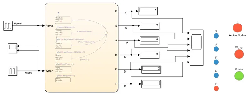
- From the above simulink diagram, it is seen that the water is not available and it is indicated by the red colour LED.
- There is continuous power supply and it is shown by the green colour LED.
- The LED named active status is indicating red colour as the system is deactivated.
- The LED named 'F' shows the finish status which is red in colour means all the processes are stop.
- Below graph shows the continuous power supply and water supply is cut off after some time.
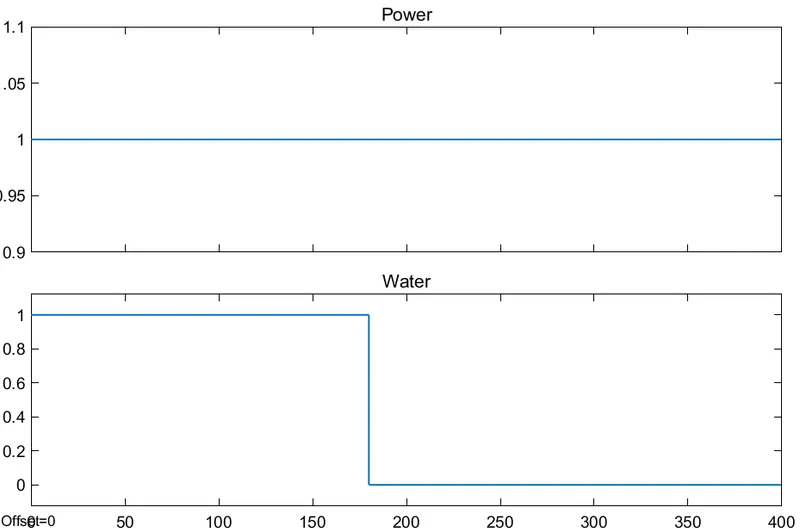
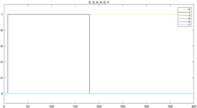
- From the above graph it is seen that the soaking process is stop as soon as the water supply is interrupetd as per the requirement time period of soaking state should be 200 sec but in the above graph it is 180 sec.
- Further processes are stoped and system is deactivated.
2. Make a Simulink chart for the 'Gear shift' logic as per below conditions:
Speed Range (kmph) Gear
0 to 15 1
16 to 25 2
26 to 40 3
41 to 60 4
Above 61 5
Give speed input while the simulation is running & display the gear number.
Answer:
Simulink model implementing gear shift logic by using the stateflow is shown in the below figure:
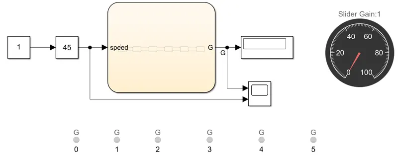
- In the simulink model, the slider gain block is used to give the speed input to the stateflow chart. By using slider gain we can change the input speed while the simulation is running and guage block is used to represent the speedometer of the vehicle.
- The stateflow chart is used to give the control logic for the gear shift according to the speed of vehicle..
- The display block is used to show the gear number.
- The lamps are used which turn ON when the vehicle is running in the particular speed.
- For example if the speed of the vehicle is 20 kmph then the LED indicating gear 2 will turn ON.
- The stateflow chart below gives the control logic for the gear shift.

- The stateflow chart shows the different state of the gear from neutral to the fifth gear.
- The input to each state is the speed. So the transition from one state to another state depends on the speed of the vehicle.
- There is the speed range for each state. The speed range is 0-15 kmph for first gear, 16-25 kmph for second gear, 26-40 kmph for third gear, 41-60 kmph for forth gear and above 61 kmph for fifth gear.
- The neutral state represents that the gear is in the neutral state at the starting of the engine.
- If the vehicle speed is 10 kmph then it is operating in the first gear and other operating state is determined by the vehicle speed. The LED indicating gear 1 will turn ON.
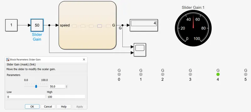
- In the above simulink model, we are changing the speed of the vehicle while the simulation is running.
- It shows that when the speed is 50 kmph, the vehicle is operating in the fourth gear.
- The speedometer shows the speed of the 50 kmph and the LED is indicating the fourth gear.
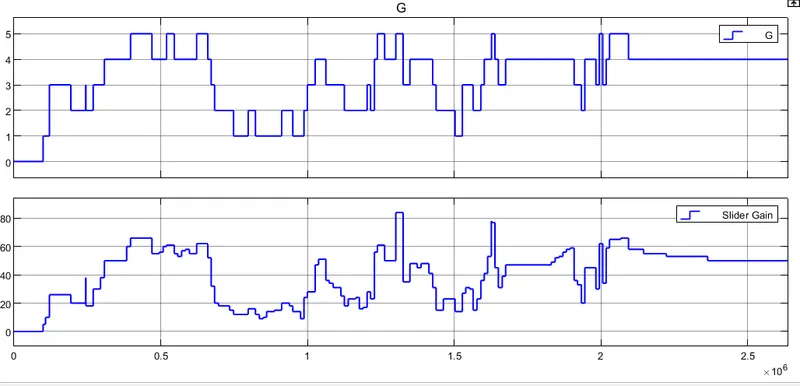
- The waveform given below shows the shifting of the gear with change in the speed of the vehicle.
- Initially when we start the engine the gear is in the neutral position and as the speed is varying the gear is also changing from one state to another.