Project
#Project
Modelling of BAJA All Terrain Vahicle (ATV) by using Continuously Variable Transmission (CVT)
Aim: To carry out the simulation of BAJA All Terrain Vehicle (ATV) by using Continuously Variable Transmission (CVT) and study the effect of parameter variation.
BAJA All Terrain Vehicle:
An all terrain vehicle is a quad bike or generally known as quad. It is defined by Americal National Standards Institute (ANSI). ATV is a light utility vehicle that travels on low pressure tires with a seat that is shradded by the operator along with handlebar for shearing control. It is designed to handle a wider variety of terrain than most other vehicles. ATVs are not street legal vehicle in most of the countries except some countries. According to the ANSI ATVs are designed to used by a single operator but some companies have developed ATVs to used by the operator and one passenger such ATVs are referred to as tandem ATVs. It is also known as OFF highway vehicles. The rider sits on and operates these vehicles like a motorcycle, but the extra wheels give more stability at slower speeds. Although most are equipped with three or four wheels, six-wheel models exist for specialized applications.
BAJA SAE:
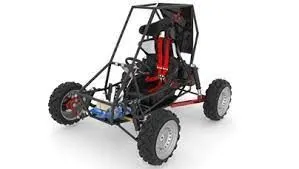
BAJA SAE is a Collegiate Design Series competition run by the Society of Automotive Engineers international (SAE International). Teams of student from the universities all over the world design and build small off road cars. The cars all have engines of the same specification. As of 2018, the engines has been an unmodified Briggs & Stratton Model 19 Vanguard engine single -cylinder with a displacement of 305cc and a power output of approximately 10 bhp (7.5 kW). The goal in BAJA SAE racing is to design, build and race off road vehicles that can withstand the harshest elements of rough terrain. The vehicles used in BAJA SAE racing are often similar in appearance to dune buggies. Before 2007 the events were called "Mini BAJA".
Continuously Variable Transmission (CVT):
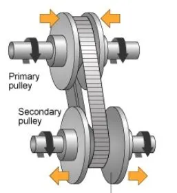
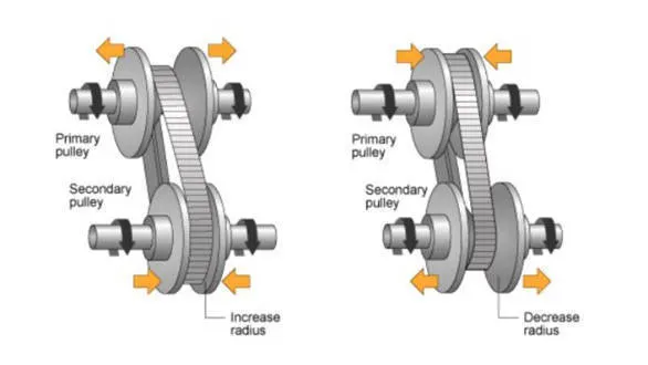
A CVT or Continuously Variable Transmission is an automatic, single speed and gearless transmission that can shift through an nifinite number of gear ratios. A continuously variable transmission is a transmission that operates on an integenous pulley system that automaticaly varies the transmission ratio, allowing an infinite variability between highest and lowest gears with no discrete steps or shifts. CVTs provide more usable power, better fuel economy and smoother driving experience than traditional transmission that uses gearboxes with fixed number of gear sets.
Simscape Model of BAJA All Terrain Vehicle by using Continuously Variable Transmission:
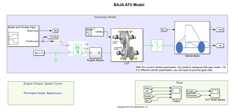
The modelling of BAJA All Terrain Vehicle (ATV) by using continuously variable transmission is shown in the above simulink model. The modelling is done to study the effect of parameter variation on the vehicle. In this model the fixed input is provided as brake input is zero and throttle input is 0.5. The input is provided by using the signal builder block and resultant output is studied for a constant input. The simulation time is kept as 200 seconds.
As per the simulink model the blocks used in the model are given as follows:
Signal Builder:
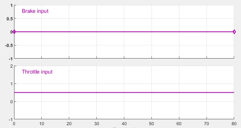
- In this model two signal builder blocks are used. One block is used here to provide the throttle and brake input to the engine. The brake input is zero and throttle input is 0.5 as shown in the below figure.
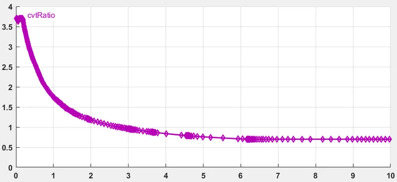
- The second block is used to give the variable gear ratio to the CVT. The figure below represents the variable cvt ratio which is given to the gearbox of the Continuously variable transmission. This curve represents the ratio of input to output angular shaft velocities.
Generic Engine:
- The generic engine block is used here to represents the BAJA engine which is internal combustion engine. The generic engine basically represent the system level model for spark ignition and diesel engines which is suitable for use at initial stages of the modelling when only basic parameters are available.
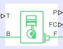
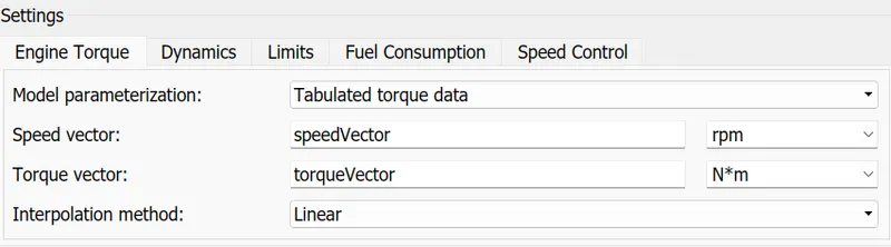
- The input parameter provided to the generic engine is shown in the above figure. The parameter for the speed and torque vector are provided from the engine speed-torque curve. The data from the speed torque curve are extracted by the data point extraction method. The 'GRABIT' is used to extract the data points from the image. The image for the engine speed torque curve is shown below.
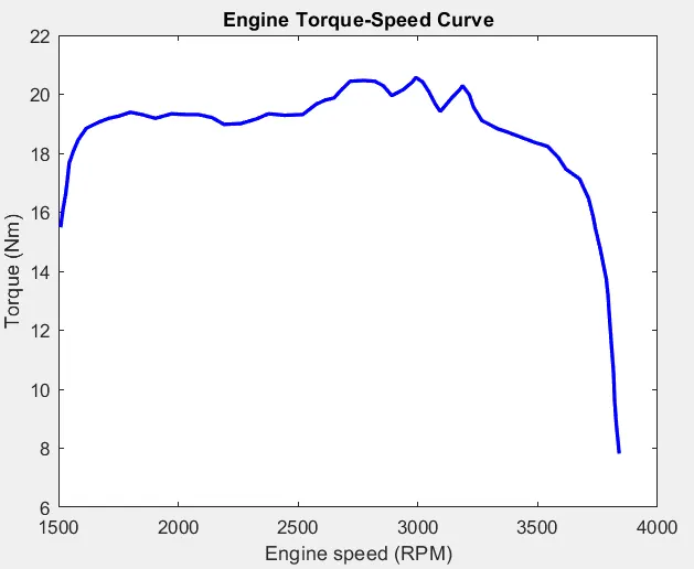
- The data points extracted from the engine speed torque curve are shown in the workspace as follows:
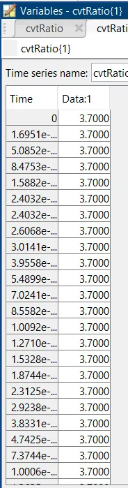
Engine Sensor:
- The engine sensor is used here to simply measured the speed of the engine which is feeded to the continuously variable transmission (CVT) as the primary pulley of the CVT is connected to the engine.
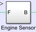
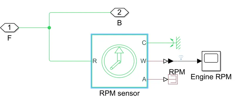
- The subsystem of the engine sensor contains the following blocks.
- The ideal rotational motion sensor block is used which measures the angular velocity of the engine.
- The scope block is used to see the speed.
- The PS terminator block is used to terminate the output physical signal. If the output physical port in unconnected the it will generate the warnings.
- The mechanical rotational reference block provide the ground.
Continuously Variable Transmission (CVT):
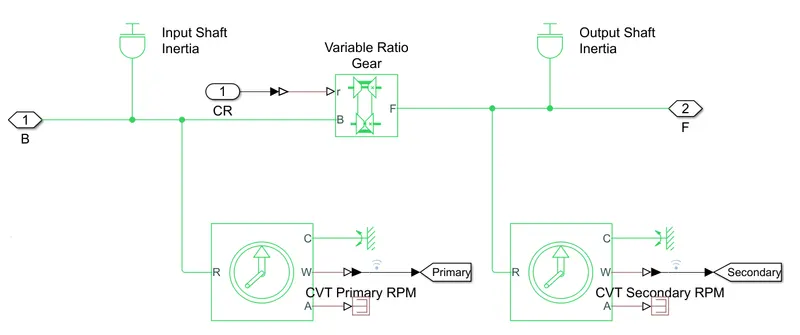
- A continuously variable transmission is represented by the following simulink model.
- The two inertia blocks are used in the model. This block represent an ideal mechanical rotational inertia. Here the input shaft inertia and output shaft inertia represent the primary and secondary pulley respectively.
- The variable ratio block represent the gearbox with variable gear ratio. The port 'r'of the block defines the ratio of input to the output angular shaft velocities.
Simple Gear:
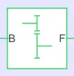
- This block provide the fixed gear ratio to the vehicle body. So that vehicle gained particular fix speed to move forward.
Vehicle body:
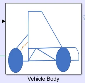
- This block provide the BAJA All Terrain Vehicle (ATV) for the simulation.
- The block shows the complete vehicle assembly with the input require to operate the engine.
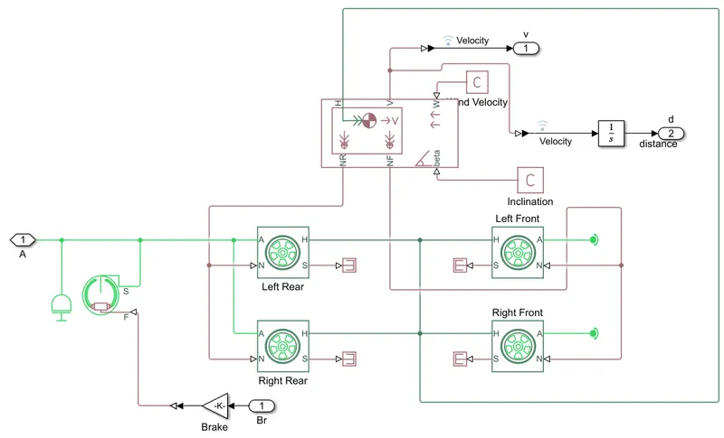
- The modelling of the BAJA All Terrain Vehicle is shown in the following figure.
-
The vehicle body block represents a two-axle vehicle body in longitudinal motion. The block accounts for body mass, aerodynamic drag, road incline, and weight distribution between axles due to acceleration and road profile. The vehicle can have the same or a different number of wheels on each axle. Optionally include pitch and suspension dynamics or additional variable mass and inertia. The vehicle does not move vertically relative to the ground.
- The tire blocks are used to represent the four tires of the ATV as it is a light utility quad bike. This block represent the longitudinal behaviour of the highway tire.
Results:
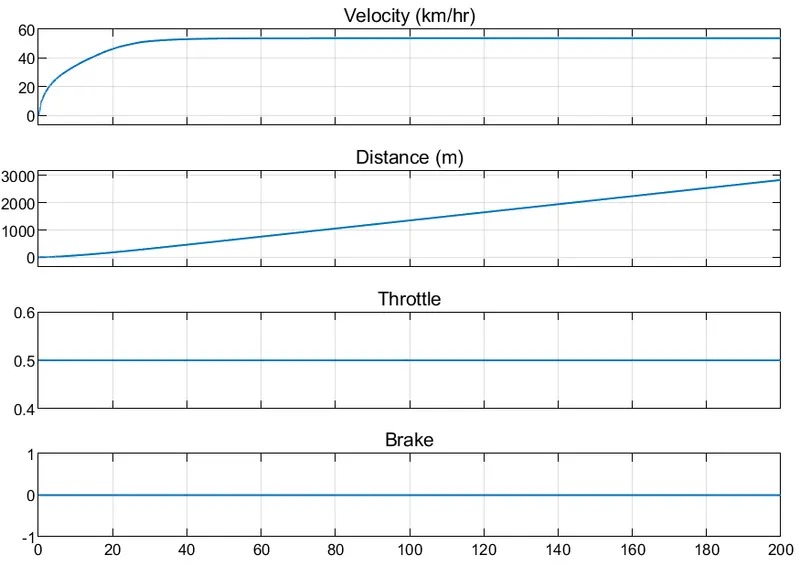
- From the above graph it is seen that the brake input is zero.
- Throttle input is 0.5 and it is constant throughout the simulation.
- Velocity of the vehicle is increasing and reaches the steady state maximum condition as the input to the system is constant throughout the simulation.
- Distance graph shows the distance travelled by vehicle.
CVT SPEED:
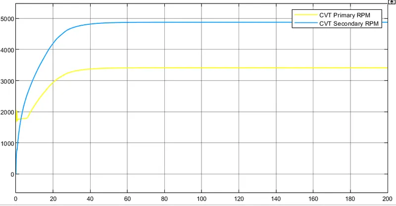
- It is seen that the RPM of the secondary pulley is greater than the primary so it is leading to over drive.
- Both the CVT primary and secondary RPM are inversely proportional to the CVT ratio.
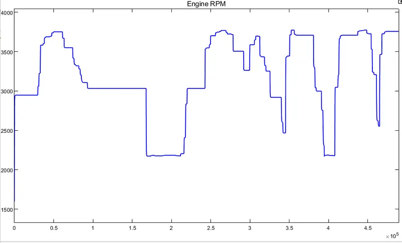
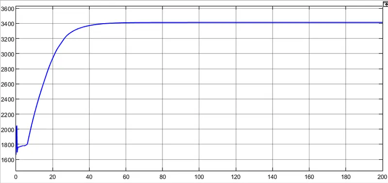
- The waveforms of the CVT primary pulley is same as the engine RPM because the primary pulley is connected to the engine shaft.
ENGINE RPM:
Simscape Model of BAJA All Terrain Vehicle by using Continuously Variable Transmission with Dashboard:
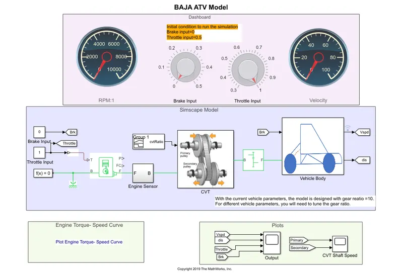
In this modelling a separate dashboard is provided. The knobs are used to give the variable input to the system. Simulation time is kept as infinity. We can varry the brake input and throttle input while the simulation is running. The initial condition to run the simulation is brake input is zero and the throttle input is 0.5. The guage are used to see the engine RPM and speed of the vehicle for varrying input values. So we have to study the effect of variable input on the system.
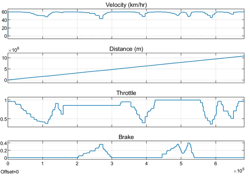
- The above graph shows the varrying brake input and throttle input.
- As from the graph, the velocity of the vehicle body is decreasing with the decreasing throttle value as it is directly proportional to the throttle input.
- The velocity of vehicle body is decreasing with the increasing brake input as it is inversely proportional to the brake input.
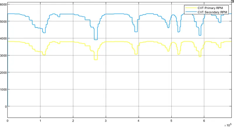
- The cvt primary RPM and secondary RPM values are decreasing in the same proportion.
- The cvt primary RPM and secondary RPM are varrying in the same manner as velocity of vehicle body with respect to the brake input and throttle input.
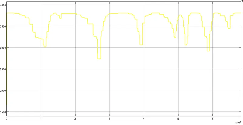
- The engine RPM and the cvt primary RPM are having same values as the primary pulley is connected to the engine.
Engine RPM:
Simscape Model of BAJA All Terrain Vehicle by using Continuously Variable Transmission with lookup table:
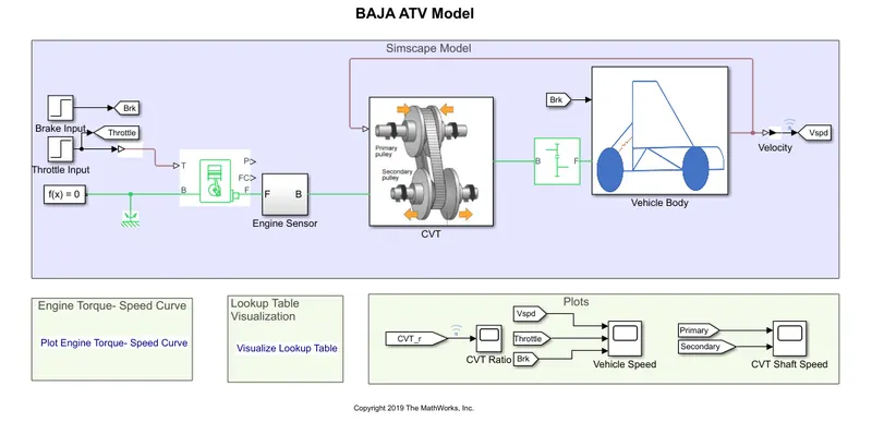
- In this model, the brake input and the throttle input are given by using step signal instead of signal builder block.
- The brake input and throttle input is constant throughout the simulation.
- The simulation time in this model is 200 seconds.
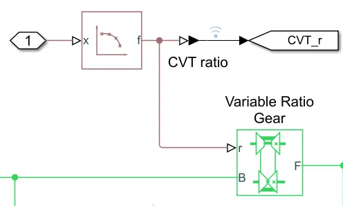
- The lookup table is used to define the cvt input ratio to the cvt block.
- The input parameter to the lookup table is shown in the below image.
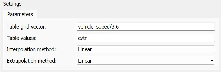
- This input parameter are define by the following curve of CVT ratio Vs Vehicle speed curve.
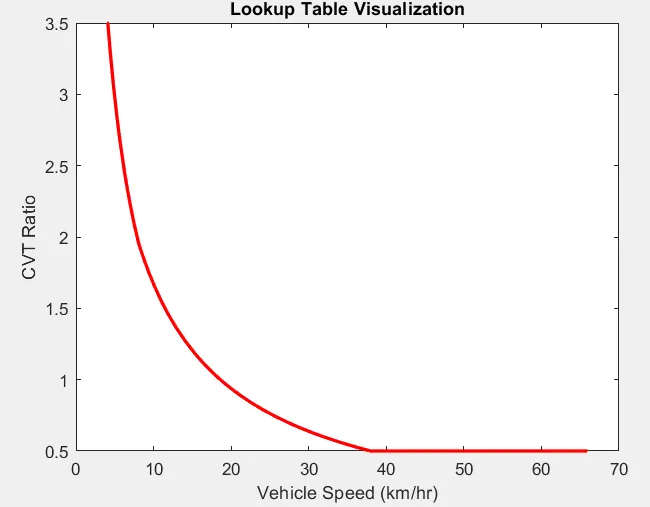
- The final cvt ratio curve from the lookup table visualization is shown in the following waveforms.
CVT ratio:
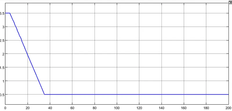
- This curve is given as a input to the variable ratio transmission block as shown in the below figure.
Results:
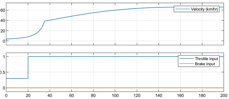
- The brake input is zero and throttle input is changing from 0.3 to 1 after 20 seconds.
- The vehicle velocity graph shows that velocity of graph is inversely proportional to the cvt ratio.
- The velocity is increasing after 20 seconds as the throttle input is increasing.
- The velocity graph is affected by the throttle input and CVT ratio both.
CVT Shaft Speed:
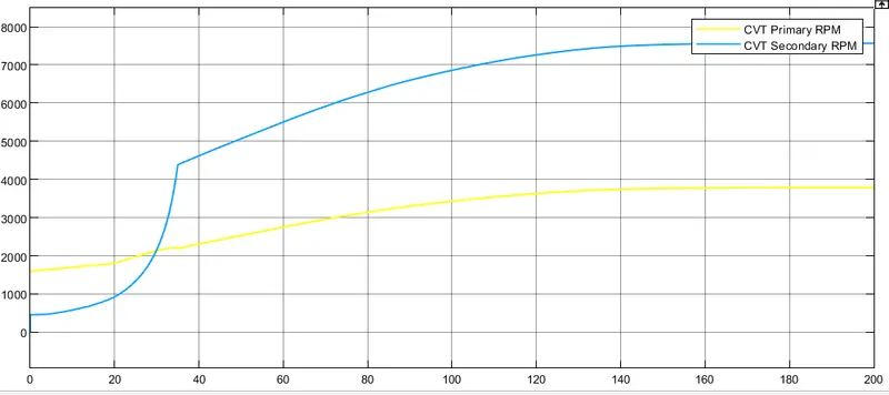
- From the above graph it is seen that the waveform of CVT secondary RPM looks similar to the vehicle velocity graph.
- CVT secondary RPM is also inversely proportional to the CVT ratio.
- The CVT secondary RPM is also affected by the throttle input and CVT ratio but CVT primary RPM is only affected by the throttle input.
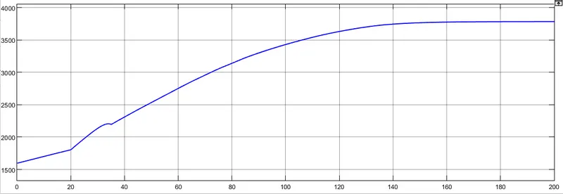
- The CVT primary RPM is similar to the engine RPM.
Engine RPM:
Simscape Model of BAJA All Terrain Vehicle by using Continuously Variable Transmission with lookup table and dashboard:
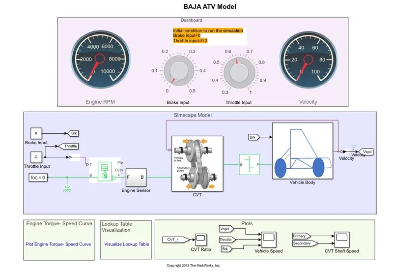
- This model is similar to the model with lookup table but with the dashboard.
- We can change the brake input and throttle input by using dashboard during simulation.
- The knobs are used to give the brake input and throttle input.
- The initial condition to run the simulation is brake input is zero and throttle input is 0.3.
CVT Ratio:
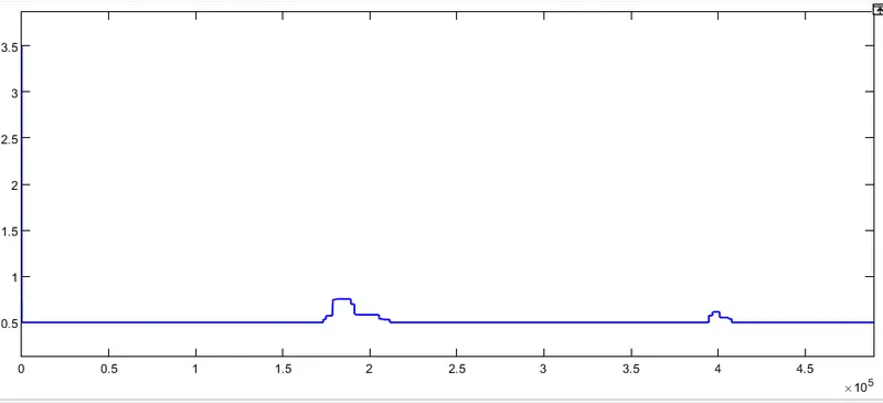
- It is seen from the above graph that the CVT ratio is affected by the brake input.
- As we increase brake input the CVT ratio increases.
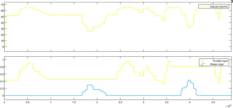
- The velocity of the vehicle is directly proportional to the throttle input and inversely proportinal to the brake input.
- The effect of CVT ratio also adds to the velocity of the vehicle as it is inversely proportional.
CVT Shaft speed:
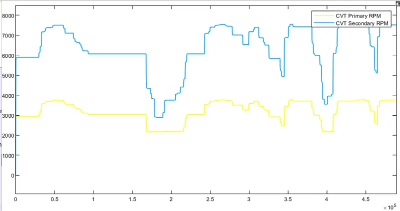
- The CVT secondary RPM in varying in the same manner as the velocity of the vehicle.
- The CVT secondary RPM is affected by the brake input, throttle input and CVT ratio.
- The CVT primary RPM is only affected by the brake and throttle input.
- The engine RPM as shown below is same as CVT primary RPM.
Engine RPM: