Week -2
#3
1. Make a Simulink model of Doorbell using solenoid block
Objective: We have to observe the physical movement of the plunger when the switch is close for 2 seconds and then released.
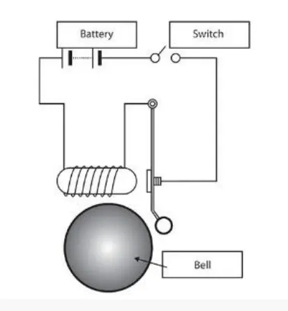
Schematic Diagram: Figure shows the schematic of the doorbell system using the solenoid block. It gives the basic overview of the doorbell system network arrangement. In the doorbell system when the switch is closed current flows through the network. When the current flows through the solenoid coil it creates the magnetic field. This magnetic field produces the linear motion of the plunger in the doorbell system.
Simulink Model:
Explanation:
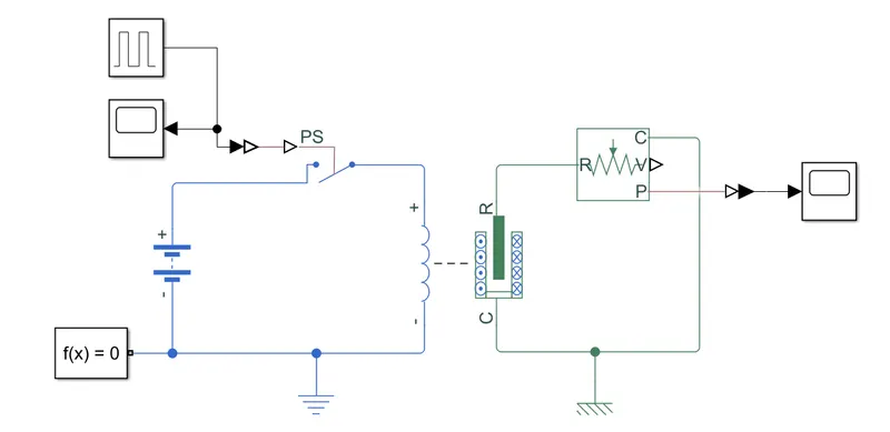
As per the simulink model the blocks used in the model are given as follows:
1. Battery: Here the 12 V battery is used to give the power supply to the solenoid through the switch.
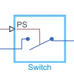
2. Switch: The switch is used to apply our required condtion as the switch is closed for 2 seconds and then released. It is controleed by external physical signal.
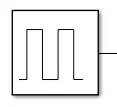
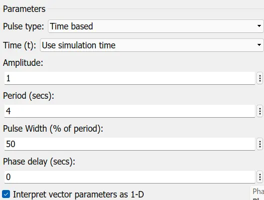
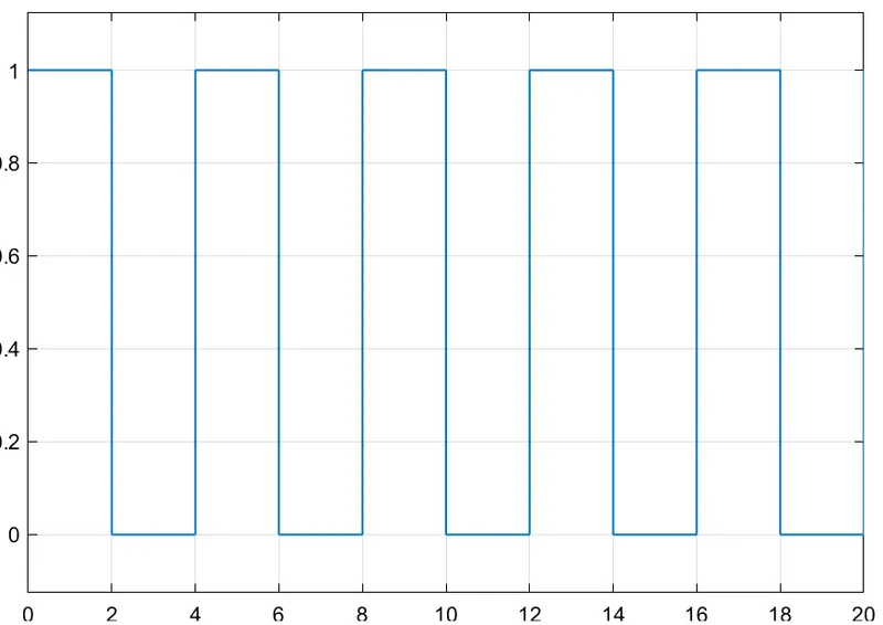
3. Pulse Generator: As the switched is operated by external signal, here the pulse generator is used to give the input signal to the switch in the form of pulses. The input parameter of the pulse generator is given in the below diagram. This pulse generator produce the pulses as shown in the waveform diagram.
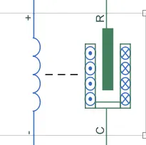
4. Solenoid: The solenoid is a type of electromagnet. It shows both electrical and mechanical characteristics. When the switch is close the current flows through the spring. It produced magnetic force and due to this force plunger (Named as R) moves towards/away from case (Named as C) depending upon initial position.
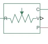
5. Ideal Translational motion sensor: This block is used to find the displacement of the plunger from initial position.
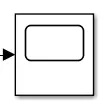
6. Scope: Here this block is used to observe the position of the plunger from motion sensor and the pulse generator input to the switch.
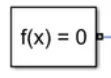
7. Solver Configuration: Each physical network represented by a connected simscape block diagram requires solver setting information for simulation. The solver configuration block specifies the solver parameters that your model needs before you can begin simulation.
8. Electrical reference: This block represents the electrical ground. A model with the electrical elements must contain electrical reference block.

9. Mechanical Translational reference: This block represents a reference point or frame for all mechanical translational ports.

Observation:
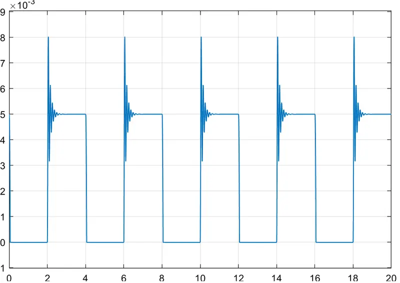
It is shown that when the switch is closed there is a plunger movement towards the case and it produces the vibrations in the system. This vibrations are shown by the spikes or oscillating waveform for the initial few seconds.
2. Use a thermistor to sense the temperature of a heater and turn ON and OFF the fan
Objective:
Temperature Source:
1. 20 degree celcius from 0 to 10 seconds
2. 27 degree celcius from 10 to 30 seconds
3. 23 degree celcius from 30 to 50 seconds
Fan condition: ON if the temperature is above 25 C, OFF otherwise.
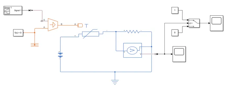
Simulink model:
Explanation:
As per the simulink model the blocks used in the model are given as follows:
1. Battery: Here the 12 V battery is used to give the power supply in the electrical network.
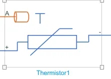
2. Thermistor: This block is a type of resistor which is temperature dependant. It gives varying resistances for varying temperature values.
3. Controlled temperature source: It is an ideal energy source in a thermal network. It maintain constant temperature difference regardless of the heat flow rate.
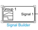
4. Signal Builder: Here the signal builder block is used to give the varying input to the controlled temperature source. It produce the output signal that shows the temperature of 293.15 K, 300.15 K and 296.15 K as shown in the waveform below.

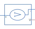
5. Voltage sensor: It is an ideal voltage sensor that convert voltage produce into physical signal. It gives the voltage measured across the resistor.
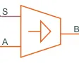
6. Switch: Here switch is used to apply the condition so that fan can turn ON above 25 degree celcius.

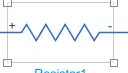
7. Resistor: Here resistor block is used to represent the fan as a load.
8. Electrical reference: This block represents the electrical ground. A model with the electrical elements must contain electrical reference block.
9. Solver Configuration: Each physical network represented by a connected simscape block diagram requires solver setting information for simulation. The solver configuration block specifies the solver parameters that your model needs before you can begin simulation.
10. Scope: Here this block is used to observe the change in the output voltage source with the change in the resistances value and also turn ON and OFF of the fan when temperature is above 25 degree celcius.
Observation:
- Image 1 shows the change in voltage with the change in the temperature. In the time duration of 0 to 10 seconds, the voltage is 9.79 mV for 23 degree celcius (293.15 K). From 10 to 30 seconds, for the temperature of 27 degree celcius voltage is 12.93 mV and for temperature of 23 degree celcius voltage is 11.05 mV, in the duration of 30 to 50 seconds.
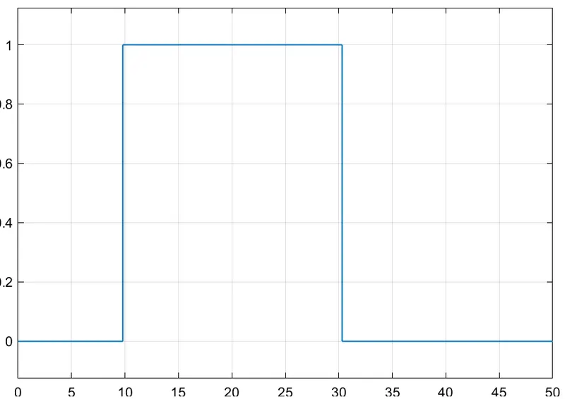
- Image 2 shows the fan condition for the change in temperature. For 10 to 30 seconds it is shown that the fan is ON as the temperature is 27 degree celcius. And the fan is OFF for 20 and 23 degree celcius.
Image 1.
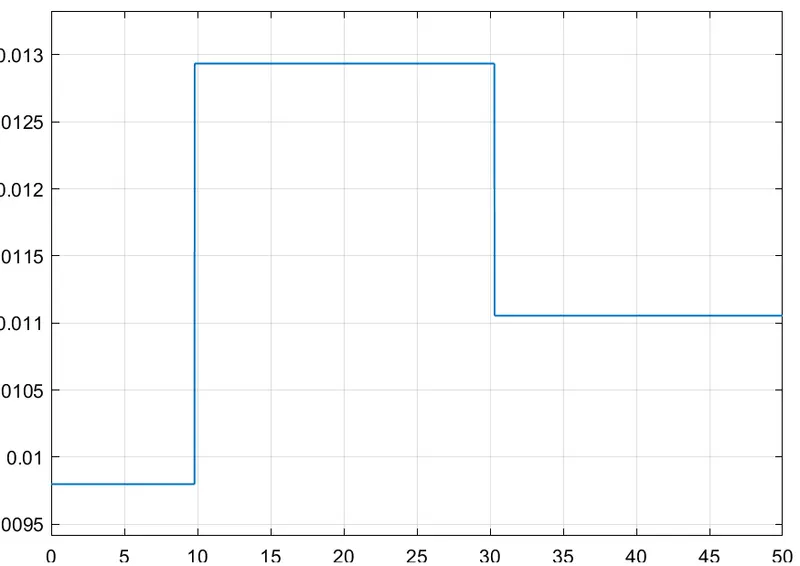
Image 2.