Week-7 Challenge: DC Motor Control
Week 7 Challenge : DC Motor Control
1. A. Explain a MATLAB demo model named ‘Speed control of a DC motor using BJT H-bridge’.
B. Comment on the armature current shoot-up from the scope results.
C. Refer to the help section of ‘The Four-Quadrant Chopper DC Drive (DC7) block’. Compare it with the H-bridge model.
A. Explain a MATLAB demo model named ‘Speed control of a DC motor using BJT H-bridge’.
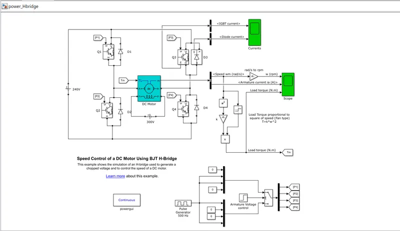
The pulse generator generates the input voltage in the circuit above. The pulse generator is then connected to the switch block through the armature voltage control block. The H-bridge is made up of four BJTs and diodes. Q1 and Q4 or Q2 and Q3 are the two transistors that are switched at the same time.
Forward motoring in Q1 and Q4
Reverse motoring in Q2 and Q3
This configuration is known as an H-bridge, which is a transistor layout that gives a circuit complete control over a typical electric DC motor. The DC motor is connected to the battery, and the DC motor's mechanical input is started as torque.
When employed in power switching applications, the Bipolar Junction Transistor (BJT) acts as an IGBT. A forward voltage Vf is created between collector and emitter when it is conducting (BJT working in the saturated area) (in the range of 1 V). As a result, the BJT device can be modelled using the IGBT block.
The gate current controlling the BJT or IGBT is not simulated by the IGBT block. A Simulink signal (1/0) is used to control the switch. The preset model is used by the DC motor (5 HP 24V 1750 rpm). It acts as a fan load simulator (where Load torque is proportional to square of speed).
When the duty cycle (given in the Pulse Generator block) is varied from 0 to 100%, the armature mean voltage can be varied from 0 to 240 V.
Four BJT/Diode pairs make up the H-bridge (BJT simulated by IGBT models). Q1 and Q4 or Q2 and Q3 are both altered at the same time. When Q1 and Q4 are activated, a positive voltage is given to the motor, and when Q1 and Q4 are turned off, diodes D2-D3 operate as free-wheeling diodes. When Q2 and Q3 are activated, a negative voltage is given to the motor, and when Q2 and Q3 are turned off, diodes D1-D4 operate as free-wheeling diodes.
With a duty cycle of 75%, the motor starts in the positive direction (mean DC voltage of 180V). The armature voltage is abruptly reversed at t=0.5 sec, and the motor runs in the other direction.
'Scope' displays the motor speed, armature current, and load torque, while 'Currents' displays the currents flowing through the BJT Q3 and diode D3.
B. Comment on the armature current shoot-up from the scope results.
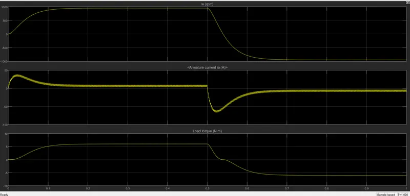
A flow of armature current, as well as speed and load torque, are depicted in the scope above.
The DC motor determines the speed and armature current, and load torque is determined using load torque proportional to square of speed. There is a sudden shootup in the beginning. In this case, the speed is increased over a period of time, and the armature current is positive at that time, while the load torque is also increasing.
There is a quick shootup and speed decreases after the time period of 0.5 seconds specified in the pulse generator. At that moment, armature current is in the negative terminal, although torque is acting in the opposite direction.
The amount of circuit action is shown as a graphical representation in the current output during the duty cycle period. In the quadrants Q3 and D3, the scope displays IGBT current and diode current passing through. In the scope, Q3 represents IGBT current and D3 represents diode current.
When the switch Q3 is turned off, the current flow starts at the beginning stage, and the diode current is at that stage.
D3 switch is ON for 0.5 sec according to pulse generator, then D3 switch is OFF for 0.5 sec, IGBT current is acted after 0.5 sec, and Q3 switch remains ON.
C. Refer to the help section of ‘The Four-Quadrant Chopper DC Drive (DC7) block’. Compare it with the H-bridge model.
A continuous 150V DC field voltage source is used to drive the 200 HP DC motor individually. An IGBT converter controlled by two PI regulators provides the armature voltage. A 515V DC bus is used to power the converter, which is created by rectification of a 380V AC 50Hz voltage source. A brake chopper has been installed between the diode rectifier and the DC7 block to limit the DC bus voltage during dynamic braking mode.
A speed regulator comes first, followed by a current regulator. The current controller uses the armature current reference provided by the speed regulator to calculate the electromagnetic torque required to reach the specified speed. To avoid rapid reference changes that could produce armature over-current and destabilise the system, the speed reference change rate follows acceleration and deceleration ramps. The current regulator regulates the armature current by calculating the duty ratios of the four IGBT devices' 5Hz pulses.
The instantaneous pulse values of IGBT devices 1 and 4 must be opposite those of IGBT devices 2 and 3 for optimum system behaviour. This gives you the average armature voltage you'll need to get the armature current you want. A smoothing inductance is connected in series with the armature circuit to limit the magnitude of the current oscillations.
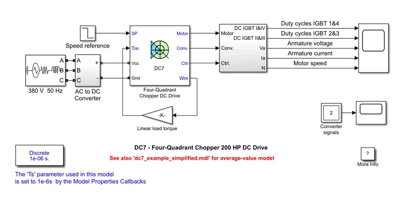
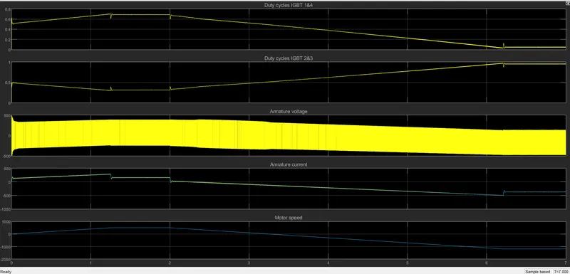
Comparision of The Four-Quadrant Chopper DC Drive (DC7) block with H-bridge model.
The motor can be operated in four separate modes in a four quadrant chopper drive, including forward driving and braking, reverse motoring and braking.
However, in a BJT H- Bridge drive, it is utilised to change the motor's direction, such as forward and reverse.
Regenerative braking is possible in a four-quadrant chopper, but not in a BJT H-bridge.
The source of a four quadrant chopper drive is an AC supply that can be corrected to a DC variable supply. The source of a BJT H-bridge is a constant DC supply.
The motor speed reference can be fed into a four quadrant chopper. The motor speed reference cannot be provided into a BJT H-Bridge.
The armature current does not reach the level of a BJT H-Bridge, but it is minimal at low voltage. During the phase transition in a BJT H-Bridge, the armature current increases.
In comparison to the H-Bridge, the chopper has a higher efficiency and requires less maintenance.
The H-Bridge circuit is used in modern battery technology chargers for EV charging. In both industrial and commercial applications, a four-quadrant operation is necessary.
To control the motor in an H-Bridge, we must change the polarity such that it turns in the opposite direction, whereas in a chopper model, we must interrupt one signal while it is controlled by another.
2. Develop a 2-quadrant chopper using simulink & explain the working of the same with the relevant results. (Refer to article - Multiquadrant operation of motor )
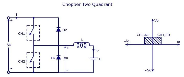
By connecting type –A and type –B choppers in parallel, a type C chopper is created. Because the freewheeling diode FD is present across the load, we will always get a positive output voltage V0. The freewheeling diode begins to conduct when the chopper is turned on, and the output voltage v0 equals Vs. The load current i0 will be reversed in direction. Regardless of whether the chopper is on or the FD conducts, the current i0 will flow towards the source and will be positive. If the chopper or diode D2 conducts, the load current will be negative. In the first quadrant, the chopper and FD work together as a type-A chopper.The chopper and D2 will operate together as a type –B chopper in the second quadrant.
The average load current may be positive or negative, but the average voltage will always be positive. The power flow can be from source to load, as in the first quadrant operation, or from load to source, as in the second quadrant action. The two choppers should not be turned on at the same time since the combined operation could cause a supply line short circuit. These types of chopper configurations are employed for regenerative braking and motoring.
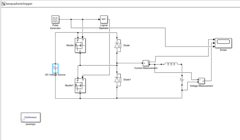
Open MATLAB and click on Simulink library block. We need a voltage measurement block and current measurement block, add both of them to the Simulink new model and powergui is must for simulation to take place. Without powergui block, the simulation won't take place.
We require a DC volatge source, choose the one that are in black colour because they are used for power electronics applications. Ant then we will be requiring MOSFET and then we require pulse generator and diode. And series RLC branch which will be converted later as a inductive load and at last add scope to the model. And logical operator as well which will be converted later to the NOT gate according to the requirement.
Then connect all the blocks according to the circuit. Now disable the measurement port for the MOSFET and Diode blocks. Once we change the logical operator to the NOT gate, connect the pulse generator output to the NOT gate operator. The reason why we are using NOT gate is to ensure that both the switches will not conduct simulatenously at the same time or together, if they do so then the supply will be short circuited. So, from gate port of one of the MOSFET is connected to the output of the pulse generator and the output from NOT gate is connected at the gate port of the another MOSFET.
So, that only one MOSFET is connected or operated at one time and next the second MOSFET is operated. And to the scope, current measurement, voltage measurementt and even if required pulse generator outputs are connected to see the waveforms.
Set the voltage to 24volts at the DC voltage source block and set the another voltage source block to 12volts (which is connected at the load side). Click the pulse generator block and set the amplitude to 10volts, so that we can clearly see the pulses and set the period time to 0.02 seconds and pulse width to 50, because we want 50% of the time to be ON and 50% time to be OFF.
And at last set the simulation time for 1 sec. Hence these are a static loads, so there won't be huge simulation time.
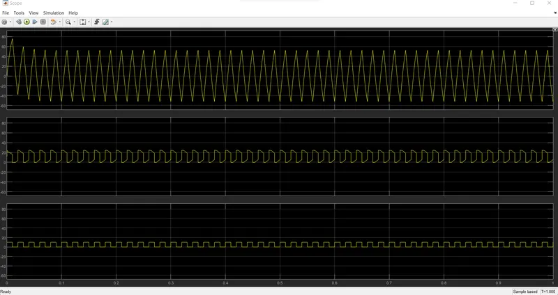
And the result is shown in the scope region. So, the first waveform is current waveform, it increases and decreases and it goes negative as well based on the switching action.
Second waveform is voltage waveform, it is not going less than zero. i.e.,maximum value is always positive and the minimum value is zero but not less than zero and it is always in the positive direction.
And the last waveform is the pulse generator waveform. i.e., the pulse generated by the pulse generator. Amplitude is given to be 10 volts.
3. Explain in a brief about operation of BLDC motor.
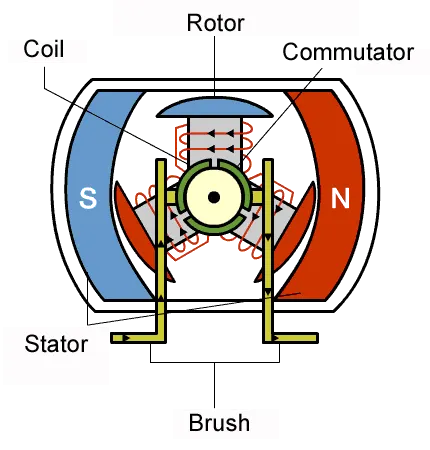
A brushless DC motor (also known as BLDC) is a permanent magnet synchronous electric motor that is powered by direct current (DC) electricity and uses an electronically controlled commutation system rather than a physically controlled commutation system to produce rotational torque in the motor. Trapezoidal permanent magnet motors are another name for BLDC motors.
BLDC motors use electrical commutation with a permanent magnet rotor and a stator with a sequence of coils, as opposed to conventional brushed type DC motors, where the brushes make mechanical contact with the commutator on the rotor to form an electric path between a DC electric source and the rotor armature windings. Permanent magnets (or field poles) move in this engine, but current carrying wires are fixed.
At the correct rotor position, the armature coils are switched electronically by transistors or silicon controlled rectifiers in such a way that the armature field is in space quadrature with the rotor field poles. As a result, the rotor rotates due to the force imposed on it. The most typical way to sense the position of the rotor is to employ hall sensors or rotary encoders, which are positioned around the stator. The sensor's rotor position feedback aids in determining when to switch the armature current.
In a DC motor, this electronic commutation system eliminates the commutator and brushes, resulting in more dependable and quieter operation. BLDC motors can run at high speeds because they don't have brushes.
BLDC motors have an efficiency of 85 to 90%, whereas brushed type DC motors have an efficiency of 75 to 80%. BLDC motors are available in a wide range of power levels, including fractional horsepower, integrated horsepower, and enormous power ranges.
Working and Operation of BLDC
The Lorentz force law states that whenever a current carrying conductor is placed in a magnetic field, it experiences a force. A BLDC motor works on the same principle as a regular DC motor. The magnet will experience an equal and opposite force as a result of the reaction force. The current carrying wire is stationary in a BLDC motor while the permanent magnet moves.
When a supply source electrically switches the stator coils, it transforms into an electromagnet and begins to produce a consistent field in the air gap. Despite the fact that the source of power is DC, switching produces an AC voltage waveform with a trapezoidal shape. The rotor continues to rotate due to the force of interaction between the electromagnet stator and the permanent magnet rotor. Consider the diagram below, which shows how the motor stator is energised by various switching states. The matching windings electrified as North and South poles when the windings were switched as High and Low signals. The North and South poles of the permanent magnet rotor align with the stator poles, causing the motor to rotate.
The generation of attraction forces (when North-South or South-North alignment) and repulsion forces (when North-South or South-North alignment) causes the motor to produce torque (when North-North or South-South alignment). This causes the motor to rotate in a clockwise manner.
The motor's continuous rotation is dependent on the coils' switching sequence. Hall sensors provide shaft position feedback to the electronic controller unit, as mentioned previously.
The controller determines which coils to energize based on the sensor's signal. When rotor poles pass close to a Hall-effect sensor, it generates Low and High level signals. The position of the shaft is determined by these signals.
Brushless DC Motors are used in a variety of applications (BLDC)
Brushless DC Motors (BLDC) are utilised for a wide range of applications in the sectors of industrial control, automotive, aviation, automation systems, health care equipment, and so on. They can handle variable loads, constant loads, and positioning. BLDC motors are used in a variety of applications.
DVD/CD players and computer hard discs
Electric cars, hybrid cars, and electric bicycles are all available.
Industrial robots, CNC machine tools, and simple belt-driven systems are all examples of automated systems.
Compressors, dryers, and washing machines
Pumps, fans, and blowers