Week - 4
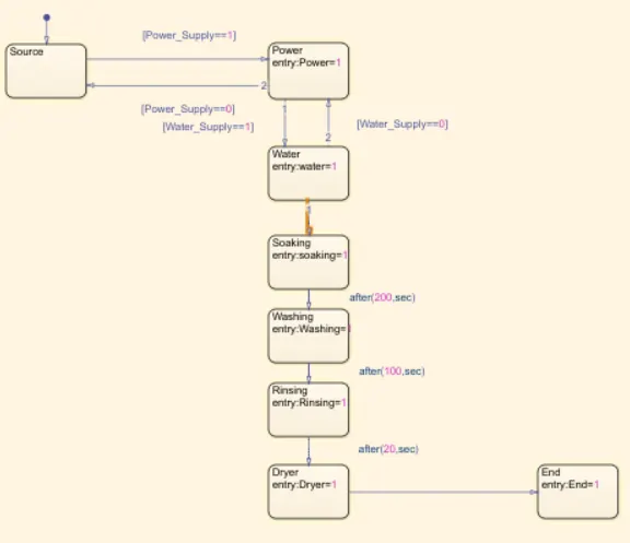
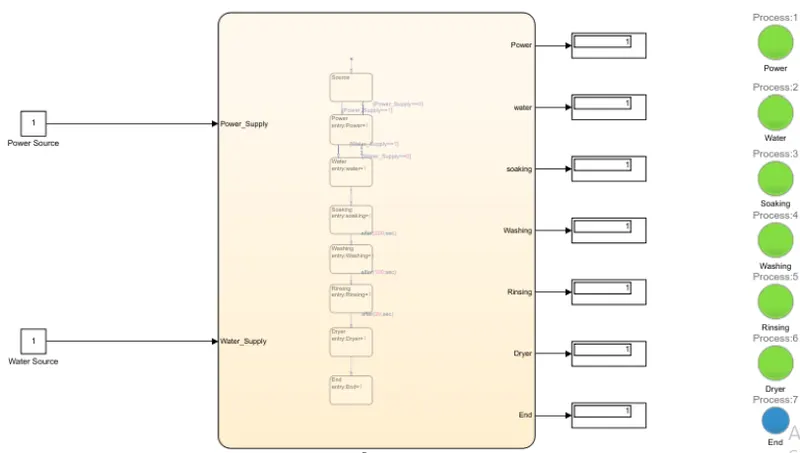
1. The Objective of the given challenge is to Implement a control logic of a "washing machine" using Stateflow according to the given sequence.
Step1: When the power supply is available, the system gets activated.
Step2: If the water supply is not available, stop the process and indicate through the LED.
Step3: The soaking time should be 200seconds and the washing time should be 100seconds.
Step4: Then rinsing happens for the next 20seconds and the dryer runs for 50seconds.
When all the steps are completed, turn ON the finished LED.
Stateflow contains state transition diagrams, flow charts, truth tables, and state transition tables in its graphical language. By describing how MATLAB algorithms and Simulink models react to input signals time-based circumstances using Stateflow. State machines, flowcharts, and truth tables are used to model system logic in control logic.
Go to the symbol panel and assign the specified variable after you've entered the input condition in the chart. Then, for the power and water supplies, provide the input values for turning them on or off. Then lamp indicator and display block display the result.
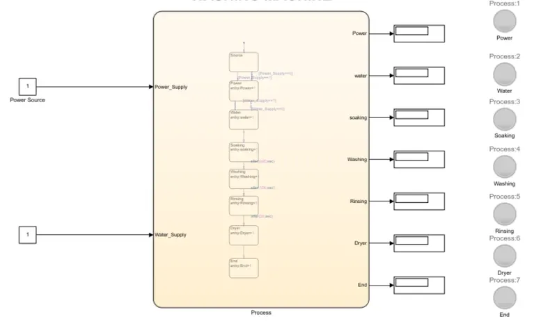
The Washing machine is connected with the power source and output display for each step and the lamp indicator is also connected.
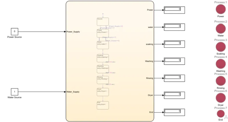
In the first case, when the Power source is 0 then there is no power supply and the water source is also 0 so the system is inactive. Hence the lamp indicators are showing red and there is no output shown in the display
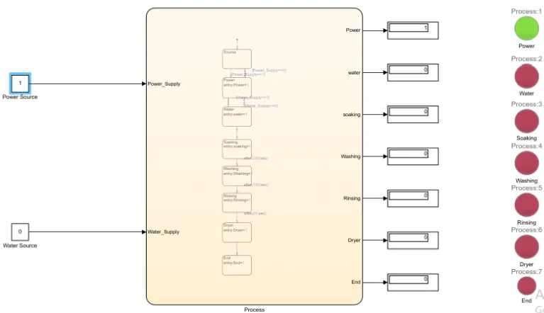
In the second case, when the power source is 1 the power supply is turned on but the water source is 0 hence there is no water supply. So, the system remains inactive again. So only the power lamp is glowing green but still, the process has not started yet.
In the third case, when the power source is 1 and the water source is also 1, then the power supply is turned on and the water supply is given to the machine and the system is active. Hence all the lamp indicators are glowing green.
2. The Objective of the given challenge is to create a model for "Gear Shifting" logic according to the given conditions.
Given Conditions:
Speed Range(kmph) Gear
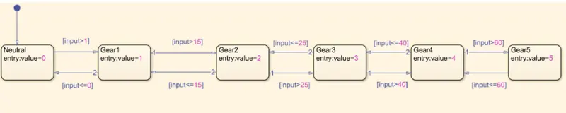
0 to 15 1
16 to 25 2
26 to 40 3
41 to 60 4
Above 61 5
In the first case, 5 different gearboxes are connected in series with different speed ranges.
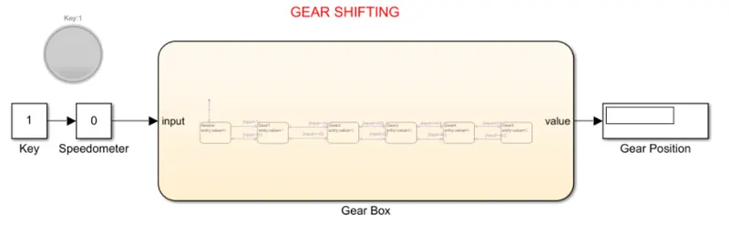
In the second case, the speedometer is connected to the gearbox to change the speed and the display is connected to know the gear position.
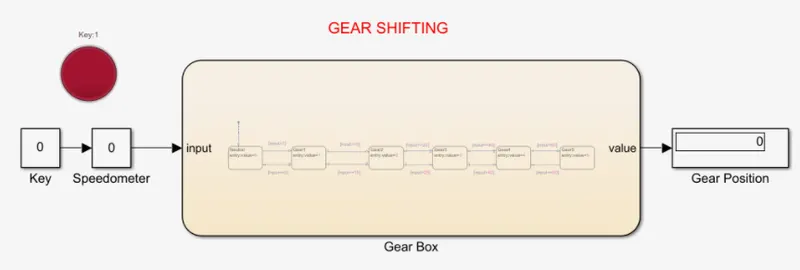
In the third case, when the key is 0 then there will be no power given to the gearbox hence the lamp is indicating red which means there is no power.
In the fourth case, when the key is 1 then the power is given to the gearbox hence the lamp will indicate green. And when the speedometer is varied the display shows the gear position.
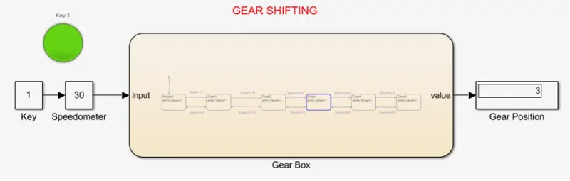
Hence this was the simulation showing the gear shifting with the given conditions.