Week-7 Challenge: DC Motor Control
Aim: Understanding DC Motor Control Drive.
Objective:
1.
- Explain a MATLAB demo model named ‘Speed control of a DC motor using BJT H-bridge’.
- Comment on the armature current shoot-up from the scope results.
- Refer to the help section of ‘The Four-Quadrant Chopper DC Drive (DC7) block’. Compare it with the H-bridge model.
2. Develop a 2-quadrant chopper using Simulink & explain the working of the same with the relevant results. (Refer to the article - Multiquadrant operation of the motor )
3. Explain in a brief the operation of the BLDC motor.
Introduction:
Bipolar Junction Transistor (BJT):
A bipolar junction transistor is a type of transistor that uses both electrons and electron holes as charge carriers. In contrast, a unipolar transistor, such as a field-effect transistor, uses only one kind of charge carrier.
The main basic function of a BJT is to amplify current it will allow BJTs to be used as amplifiers or switches to produce wide applicability in electronic equipment include mobile phones, industrial control, television, and radio transmitters.
Chopper:
In electronics, a chopper circuit is any of numerous types of electronic switching devices and circuits used in power control and signal applications. A chopper is a device that converts fixed DC input to a variable DC output voltage directly.
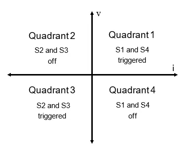
In Quadrant I:
- When S1 is turned ON: When S1 is on, the switches S1 and S4 are triggered, the output voltage (v_o) and output current (i), both are positive and the power flows from the source to load and the inductor stores the energy. The motor rotates in the forward direction and therefore it is called forward motoring.
- When S1 is turned OFF: When S2 is off, the Switch S4 and diode D2 are triggered, output current (i), is positive and the output voltage (v_o) will be zero and the inductor will release energy.
- The Torque and the speed are positive.
In Quadrant II:
- When S2 is turned ON: Assuming the motor is running in the forward direction. Switch S2 and diode D4 are triggered; Output voltage (v_o) becomes zero. The negative output current is attained due to the E and the machine behaves as the generator and the inductor stores energy.
- When S2 is OFF: In this situation, D1 and D4 are triggered and the output current is negative. The inductor releases energy using diodes D4 and D1, the power flows from the load to the source. This is forward braking.
- The Torque is negative and the speed is positive.
In Quadrant III:
- When S3 is ON: The Switches S3 and S2 are triggered and the Output voltage (v_o) and the output current (i) are negative and the power flows from source to load. The inductor stores the energy, the motor rotates in the reverse direction.
- When S3 is OFF: When the switch is off, the S2 and the diode D4 are triggered. The output current is negative and the output voltage is zero. The Polarity of back EMF is reversed.
- The speed and torque are negative.
.In Quadrant IV:
- When S4 is ON: The motor is running in the reverse direction and the switch S4 and diode D2 are triggered output voltage is zero and the machine behaves as a generator and the inductor stores the energy.
- When S4 is OFF: The diode D2 and Diode D3 are triggered. The diodes D2 and D3 are triggered. The output voltage becomes negative and the output current is positive. It is called reverse braking.
- The torque is positive and the speed is negative.
Solution:
Q. 1. a. Explain a MATLAB demo model named ‘Speed control of a DC motor using BJT H-bridge’.
Ans.:
The Bipolar Junction Transistor (BJT) when used for power switching applications, operates as an IGBT. When it is conducting (BJT operating in the saturated region), a forward voltage Vf is developed between collector and emitter (in the range of 1 V). Therefore, the IGBT block can be used to model the BJT device.
The IGBT block does not simulate the gate current controlling the BJT or IGBT. The switch is controlled by a Simulink® signal (1/0). The DC motor uses the preset model (5 HP 24V 1750 rpm). It simulates a fan type load (where Load torque is proportional to the square of speed). The armature means voltage can be varied from 0 to 240 V when the duty cycle (specified in the Pulse Generator block) is varied from 0 to 100%.
The H-bridge consists of four BJT/Diode pairs (BJT simulated by IGBT models). Two transistors are switched simultaneously: Q1 and Q4 or Q2 and Q3. When Q1 and Q4 are fired, a positive voltage is applied to the motor, and diodes D2-D3 operate as free-wheeling diodes when Q1 and Q4 are switched off. When Q2 and Q3 are fired, a negative voltage is applied to the motor, and diodes D1-D4 operate as free-wheeling diodes when Q2 and Q3 are switched off.
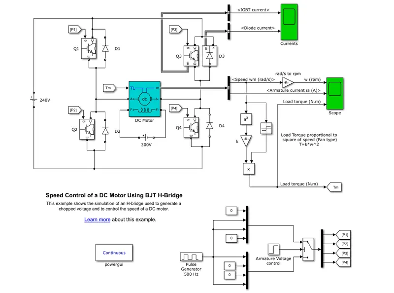
Simulation of the model (Speed control of a DC motor using BJT H-bridge) on default parameters as 75% Duty cycle:
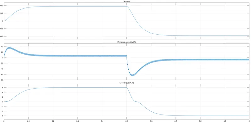
The reason why there is sudden shooting up of current in the motor is explained in the following points:
- The DC resistance of rotor winding is minimum, thus when the power is switched ON it would draw a current equal to V/R, which would be very high and if the motor does not rotate then the winding would burn out. But when the motor starts rotating then a back EMF is built with opposes the input EMF and the resultant EMF is very small to maintain the current within the limit which would always be a function of RPM.
- Inrush current of a DC motor is given by i=(V−E)/r where r is the armature resistance, V is the terminal voltage and E is the developed back emf which is directly proportional to the speed of the motor (N). During starting the motor was initially standstill, hence the speed of the motor (N) as well as back emf (E) is zero. It means that the inrush current during start is only V/r. For a DC motor, the armature resistance is very small hence the inrush current drawn is very high. As the motor starts rotating, E develops and hence current value falls.
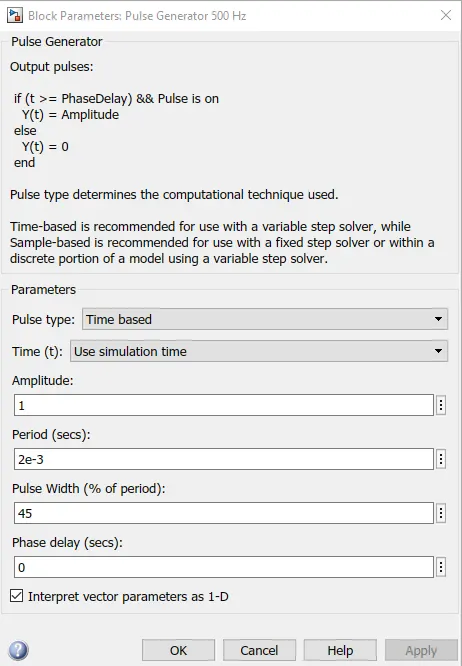
To reduce the shoot up of armature, we can reduce the pulse width to 45% which means the duty cycle will be kept at 45%.
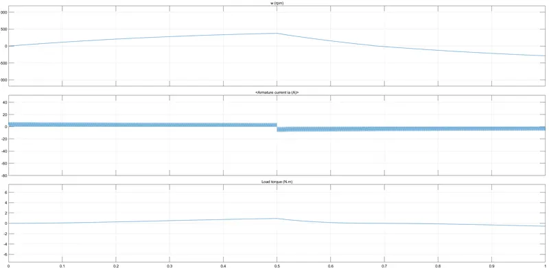
Now, the above graph shows the results obtained by changing the duty cycle to 45%.
The armature current has a significant stable current flow and hence the sudden shoot-up of current is reduced as seen in the graph is somewhat smooth.
- The current value obtained was 5.97A for the positive side and 8.23 A after changing the polarity.
- Earlier the motor speed was 950rpm which was later obtained was around 375rpm.
- For the 45% duty cycle, the torque shows a drop from 6 Nm to 1 Nm because the torque is proportional to the current flowing to the armature.
b. Refer to the help section of ‘The Four-Quadrant Chopper DC Drive (DC7) block’. Compare it with the H-Bridge model.
Ans.:
- The Stability of the voltage and current supply is higher in the four-quadrant compared to BJT as the four-quadrant uses the step-by-step ramping strategy for the change in the motor direction whereas the stability is lost.
- Regenerative braking is possible in four-quadrant but not in BJT.
- It is widely used in the automobile sector to control DC motor speed and direction in Four-quadrant. Whereas the BJT is used in robotics and electro-mechanical devices to control DC motor speed and direction.
- The current values are continuous in BJT and In Four Quadrants; it is chopped so that the simulation takes less time.
- To change the direction of the motor, current signals are interrupted in four quadrants. Whereas in BJT the polarity of the current needs to be changed.
- The main advantage of the Four-quadrant is that it operates in all four quadrants but BJT can move only in two directions.
- Four Quadrants provides better efficiency and operates at high power levels when compared to BJT that operates at moderate power levels.
c. Refer to the help section of ‘The Four-Quadrant Chopper DC Drive (DC7) block’. Compare it with the H-bridge model.
Ans.:
- The Stability of the voltage and current supply is higher in the four-quadrant compared to BJT as the four-quadrant uses the step-by-step ramping strategy for the change in the motor direction whereas the stability is lost.
- Regenerative braking is possible in four-quadrant but not in BJT.
- It is widely used in the automobile sector to control DC motor speed and direction in Four-quadrant. Whereas the BJT is used in robotics and electro-mechanical devices to control DC motor speed and direction.
- The current values are continuous in BJT and In Four Quadrants; it is chopped so that the simulation takes less time.
- To change the direction of the motor, current signals are interrupted in four quadrants. Whereas in BJT the polarity of the current needs to be changed.
- The main advantage of the Four-quadrant is that it operates in all four quadrants but BJT can move only in two directions.
- Four Quadrants provides better efficiency and operates at high power levels when compared to BJT that operates at moderate power levels.
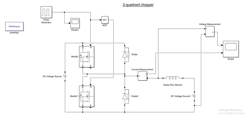
Q. 2. Develop a 2-quadrant chopper using Simulink & explain the working of the same with the relevant results. (Refer to the article - Multiquadrant operation of the motor )
Ans.:
- To create a two-quadrant chopper circuit model, we select the MOSFET which acts as a gate that is connected with a diode.
- The ends of the diode are connected to the current measurement.
- The series RLC branch end is connected to the current measurement and the DC voltage source.
- The Pulse generator is connected to the MOSFET to give a signal to the gate.
- After Connecting a Power GUI is added to show a continuous flow.
- Save the model and run it.
- Observe the plots.
Q.3. Explain in a brief the operation of the BLDC motor.
Ans.:
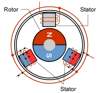
A brushless DC electric motor (BLDC motor or BL motor), also known as an electronically commutated motor (ECM or EC motor) or synchronous DC motor, is a synchronous motor using a direct current (DC) electric power supply. It uses an electronic closed-loop controller to switch DC currents to the motor windings producing magnetic fields which effectively rotate in space and which the permanent magnet rotor follows. The controller adjusts the phase and amplitude of the DC pulses to control the speed and torque of the motor. This control system is an alternative to the mechanical commutator (brushes) used in many conventional electric motors.
The construction of a brushless motor system is typically similar to a permanent magnet synchronous motor (PMSM), but can also be a switched reluctance motor, or an induction (asynchronous) motor. They may also use neodymium magnets and be outrunners (the stator is surrounded by the rotor), in runners (the rotor is surrounded by the stator), or axial (the rotor and stator are flat and parallel).
The advantages of a brushless motor over brushed motors are high power-to-weight ratio, high speed, nearly instantaneous control of speed (rpm) and torque, high efficiency, and low maintenance. Brushless motors find applications in such places as computer peripherals (disk drives, printers), hand-held power tools, and vehicles ranging from model aircraft to automobiles. In modern washing machines, brushless DC motors have allowed the replacement of rubber belts and gearboxes by a direct-drive design.
- The construction of a brushless motor system is typically similar to a permanent magnet synchronous motor (PMSM), but can also be a switched reluctance motor, or an induction (asynchronous) motor. They may also use neodymium magnets and be outrunners (the stator is surrounded by the rotor), in runners (the rotor is surrounded by the stator), or axial (the rotor and stator are flat and parallel).
- The advantages of a brushless motor over brushed motors are high power-to-weight ratio, high speed, nearly instantaneous control of speed (rpm) and torque, high efficiency, and low maintenance.
- Brushless motors find applications in such places as computer peripherals (disk drives, printers), hand-held power tools, and vehicles ranging from model aircraft to automobiles.
- In modern washing machines, brushless DC motors have allowed the replacement of rubber belts and gearboxes by a direct-drive design.
- In brushless DC motors, an electronic servo system replaces the mechanical commutator contacts.
- An electronic sensor detects the angle of the rotor and controls semiconductor switches such as transistors which switch current through the windings, either reversing the direction of the current or, in some motors turning it off, at the correct angle so the electromagnets create torque in one direction.
- The elimination of the sliding contact allows brushless motors to have less friction and longer life; their working life is only limited by the lifetime of their bearings.
- Brushed DC motors develop a maximum torque when stationary, linearly decreasing as velocity increases. Some limitations of brushed motors can be overcome by brushless motors; they include higher efficiency and lower susceptibility to mechanical wear.
- These benefits come at the cost of potentially less rugged, more complex, and more expensive control electronics.
- A typical brushless motor has permanent magnets that rotate around a fixed armature, eliminating problems associated with connecting current to the moving armature.
Results:
- For the BJT H-Bridge:
We can observe from the graphs that the decrease in the duty cycle affects the transition time and makes sure that the additional current isn’t passed and therefore showing the sharp drop at half of the duration.
The graph at 75% Duty Cycle:
The graph at 45% Duty Cycle:
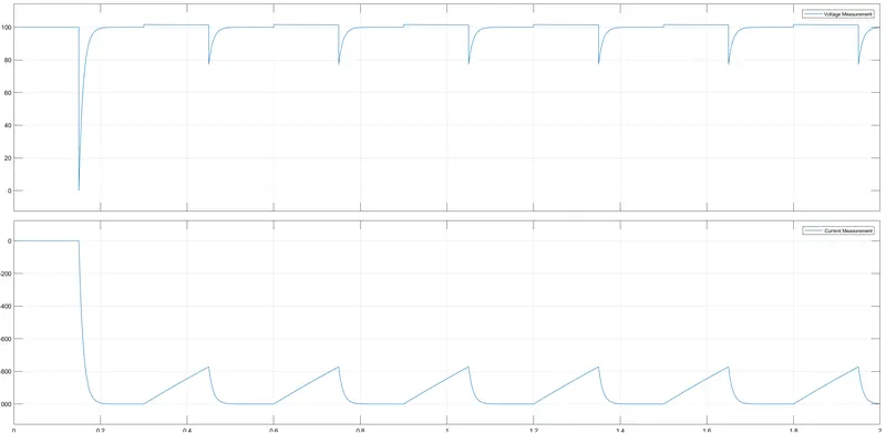
- For the Two Quadrant Chopper:
The voltage is positive and the current can be seen as fluctuating source.
Graph:
Learning Outcomes:
- Learned to check the BJT H-bridge and Four-quadrant DC drive.
- Learned to create blocks based on the circuit diagrams.
References: