Week-7 Challenge: DC Motor Control
1)MATLAB Model of speed control of h bridge controller
MATLAB demo model of “speed control of a DC motor using BJT H-Bridge”.
The BJT (Bipolar Junction Transistor) when used for power switching applications, operates as an IGBT. when it is conducting (The BJT operates at the saturation region), a forward voltage Vf is developed between Collector and Emitter in the range of one volt. Therefore the IGBT blocks can be used to model BJT devices.
The IGBT block does not simulate the gate current controlling the BJT or IGBT. The switch is controlled by a Simulink (1/0).
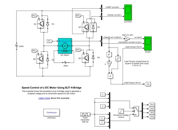
Simulink model of speed control of DC motor using BJT H-bridge is shown below
Block used: -
Ideal DC voltage source –Amplitude(v) of the block entered with a value of 240.
IGBT: - Implements an IGBT device in parallel with a series RC snubber circuit. In on state the IGBT model has internal resistance (Ron=0.001 Ohms) and Inductance (Lon=0 H) in off state IGBT model has infinite impedance, Snubber resistance Rs=1e5 with a snubber capacitance of inf.
DC machine: -Implements a (wound-field or permanent magnet) DC machine. For the wound-field DC machine, access is provided to the field connections so that the machine can be used as a separately excited, shunt-connected, or series-connected DC machine. The model selected 5HP 240V 1750RPM Field:300V with a mechanical input of Torque TL and the field type selected as a wound in configuration
Diode: - Implements a diode in parallel with a series RC Snubber circuit. In on-state the diode model has an internal resistance(Ron) as 0.001 with a forward voltage of 0.8V with a snubber resistance of inf value and a snubber capacitance selected the value as zero.
BusSelector: -This block accepts a bus as input which can be created from a Bus Creator, Bus Selector, or a block that defines its output using a bus object. The left Listbox shows the signals in the input bus. Use the Select button to select the output signals. The right Listbox shows the selections. Use the Up, Down, or Remove button to reorder the selections. Check 'Output as virtual bus' to output a single bus signal.
Gain:- Element-wise gain (y = K.*u) or matrix gain (y = K*u or y = u*K).
Math: - Mathematical functions including logarithmic, exponential, power, and modulus functions. When the function has more than one argument, the first argument corresponds to the top (or left) input port. The selected function is square here to calculate the square value of the input.
Product: -Multiply or divide inputs. Choose element-wise or matrix product and specify one of the following: a) * or / for each input port. For example, **/* performs the operation 'u1*u2/u3*u4'.b) A scalar value specifies the number of input ports to be multiplied. For example, 2 performs the operation 'u1*u2'.
Signum: - For real inputs, output 1 for positive input, -1 for negative input, and 0 for 0 input. For complex floating point inputs, the outputs follow sign(u) = u ./ abs(u).
Scope: - To display the graphical representation of the output.
Goto/From: - Goto sends signals to the from the block that have the specified tag. From tag receives signals from the goto block with the specified tag
Step: Output a step with a step time of 0.5 with an initial value of 0 and a final value of 1.and the output data type selected as double.
Constant: - output the constant specified by the constant value parameter.
Switch: -Pass through input 1 when input 2 satisfies the selected criterion; otherwise, pass through input 3. The inputs are numbered top to bottom (or left to right). The first and third input ports are data ports, and the second input port is the control port. The criteria for control port 2 are u2 >= Threshold, u2 > Threshold or u2 ~= 0.
Pulse Generator: - Output pulses if (t >= PhaseDelay) && Pulse is on Y(t) = Amplitude else Y(t) = 0 end,Pulse type determines the computational technique used.
Time-based is recommended for use with a variable step solver, while Sample-based is recommended for use with a fixed step solver or within a discrete portion of a model using a variable step solver. Here Amplitude is one with a period 2e-3apulse width percentage is 75 and phase delay is zero.
Current output from IGBT and Diode as shown below
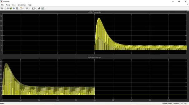
From the curves, up to the first half, the diode gives the 10A current with a spike and after that, the IGBT will give the output of the same with the higher value in the spike.
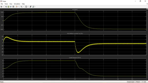
With a 75% pulse width (duty-cycle) the armature current produces a spike at an interval of 0.5seconds in the first 0.5sec Positive armature current and a positive current spike is developed, This current spike can be controlled by varying the percentage value of pulse width from the parameter of the pulse generator.
Output Curve of 75% pulse width condition is shown below
After varying the value of pulse width percentage to 50% the output plot of armature current shows that the current spike in the first 0.5sec is reduced and the armature current is reduced to its peak value to 8A approximately. The current spike in the second half cycle remains there to remove the negative voltage spike we have to reduce the duty cycle again.
Output Curve of 50% pulse width condition is shown below
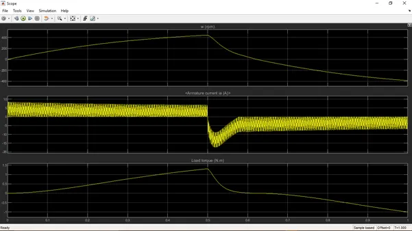
Varying the value of pulse width to 45% then the current spike in the positive half cycle and in the negative half cycle getting removed and the peak value of armature current is reduced to a value of 7.6A and the higher value of current spike is removed.
Output Curve of 45% pulse width condition is shown below
DC7 four-quadrant chopper model
The 200HP DC motor is separately Excited with a constant 150V DC field voltage source. The armature voltage is provided by an IGBT converter controlled by two PI regulators. The converter is fed by a 515 V DC bus obtained by rectification of a 380 V AC 50Hz voltage source. In order to limit the DC bus voltage during dynamic braking mode, a braking chopper has been added between the diode rectifier and the DC7 block.
The first regulator is a speed regulator, followed by a current regulator. The speed regulator outputs the armature current reference (in p.u.) used by the current controller in order to obtain the electromagnetic torque needed to reach the desired speed. The speed reference change rate follows acceleration and deceleration ramp in order to avoid sudden reference changes that could cause armature over current and destabilize the system.
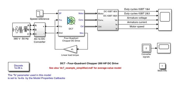
Simscape Model of DC7 Four Quadrant DC drive is shown below
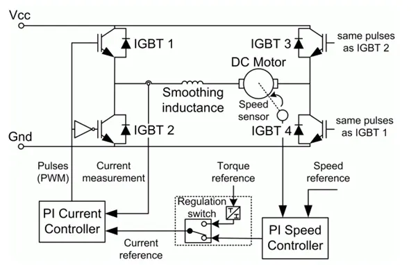
The Four Quadrant Chopper DC Drive block uses these blocks from the electric Drives/Fundamental drive block library are speed controller(DC), Regulator Switch, Current controller(DC), Chopper
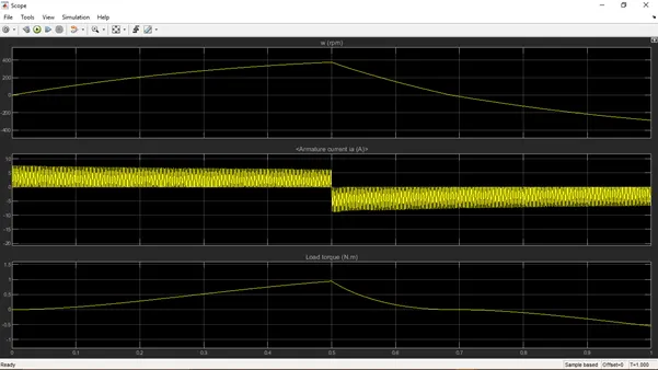
In the four-quadrant operation the first quadrant represents the forward motoring, the second quadrant represents forward braking third quadrant represents reverse motoring, and the final one the fourth quadrant represents reverse braking.
Output scope of four-quadrant DC7 chopper
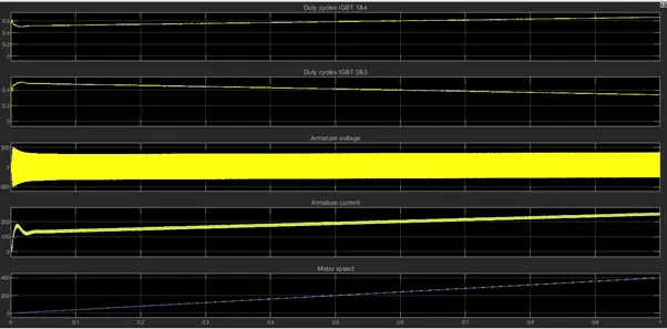
Comparison
While comparing with H-Bridge DC7 have operations in four quadrants such as forward motoring, forward braking, reverse motoring, reverse braking but h bridge handling two operations such as forward motoring and reverse motoring. Regenerative braking concept is not possible in H bridge (instead of that Dynamic braking is used in it) type but it is possible in DC7 four-quadrant chopper type Efficiency of four-quadrant DC7 chopper is higher than that of H bridge. H bridge is commonly used in robotics also in industrial applications, four-quadrant DC Choppers are used in Electric vehicles and Hybrid vehicles.
2)Modelling Of Simulink Model of the 2-quadrant chopper
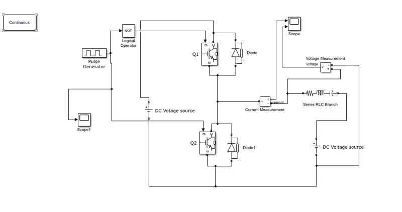
Two quadrant chopper block represents a two-quadrant controlled chopper for converting a fixed DC input to a variable DC output. In the case of a two-quadrant operation, two switching blocks will use.
Blocks Used
Pulse Generator: - it is used to create pulses from given input voltage here it is used to create switching operation of the IGBT block
Scope: -used to plot the output curve.
Logical Operator/Not: - Not operator is used to implement one circuit operation at one time.
DC Voltage Source: - used to provide input voltage to the switching device and to run the load.
Diode: - Implements a diode in parallel with a series RC snubber circuit. In on-state, the Diode model has an internal resistance (Ron) and inductance (Lon). For most applications, the internal inductance should be set to zero. The Diode impedance is infinite in off-state mode.
IGBT: - Implements an IGBT device in parallel with a series RC snubber circuit. In on-state, the IGBT model has internal resistance (Ron) and inductance (Lon). For most applications, Lon should be set to zero. In off-state, the IGBT model has infinite impedance.
Current Measurement: -Ideal current measurement. The Output signal parameter is disabled when the block is not used in a phasor simulation. The phasor simulation is activated by a Powergui block placed in the model.
Series RLC Branch: -Implements a series branch of RLC elements.
Use the 'Branch type' parameter to add or remove elements from the branch.
Operation
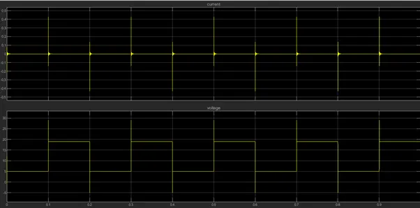
Pulse Generator creates an input pulse to switch the IGBT Q1 and IGBT Q2 alternatively and the RLC load will get a current with a varying value of –ve positive and a voltage with a positive value and a zero value
The pulse Generator output is shown below
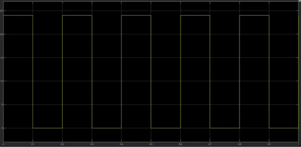
Here amplitude of the pulse generator selected as 24 with a delay of zero so it starts from the value of 24V and holds the value for 0.1 sec and then it returns to zero.
Scope result of Current and voltage measurements is shown below
3)Operation of BLDC Motor
BLDC or Brushless DC Motor is a permanent magnet synchronous electric motor that is driven by DC(direct current) electricity and it accomplishes an electronically controlled communication system (communication is the process of producing rotational torque in the motor by changing phase currents through it at appropriate times ) instead of a mechanical commutation system. BLDC motors are also referred to as trapezoidal permanent magnet motors.
BLDC motor works on the principle similar to that of a conventional DC Motor, that is the Lorentz force law which states that whenever a current-carrying conductor placed in a magnetic field it experiences a force. As a consequence of reactance force, the magnet will experience an equal and opposite force. In the case of, BLDC motor, the current-carrying conductor is stationary while the permanent magnet moves. When the stator coils are electrically switched by a supply source, it becomes an electromagnet and starts producing the uniform field in the air gap. Through the source of supply is DC, switching makes to generate an AC voltage waveform with trapezoidal shape. Due to the force of interaction between electromagnet stator and permanent magnet rotor continuous to rotate
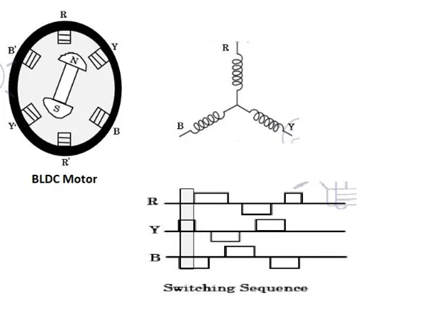
The motor stator is excited based on the different switching states, with the switching of windings as high and low signals, corresponding winding energized as north and south poles align with stator poles causing motor rotates. The motor produces a torque because of the development of attraction forces (when North-South or South-North alignment) and repulsion forces (when North-North or south-south alignment). In this way motor moves in a clockwise direction. Based on the signal from hall sensors the controller decides particular coils to energize. Hall effect sensors generate Low and high-level signals whenever rotor poles pass near to it. These signals determine the position of the shaft
The Controller unit of the BLDC motor consists of an inverter bridge electronic controller and hall effect sensor.
Advantages of BLDC motor
It has a mechanical commutator and associated problems.
High efficiency due to the use of permanent magnet rotor
High speed of operation even in loaded and unloaded conditions due to the absence of brushes that limits the speed
Smaller motor geometry and lighter in weight than both brushed type DC and induction AC motors
Long-life as no inspection and maintenance is required for commutator system
Higher dynamic response due to low inertia and carrying windings in the stator
Less electromagnetic interference
Quiet operation (or low noise) due to absence of brushes
Disadvantages of BLDS
These motors are costly
The electronic controller required to control this motor is expensive
Not much availability of many integrated electronic control solutions, especially for tiny BLDC motors
Requires complex drive circuitry
Need of additional sensors
Applications of BLDC
Widely used in computer hard drives and DVD Players, EV , hybrid Vehicles, electric bicycles, industrial robots, CNC machine tools, washing machine compressors and dryers, fan pumps and blowers
Referance:-Matlab help and Sample files