Week - 4
Aim of the project: -
To Implement the control Logic of a “washing machine” using Stateflow.
To create a Simulink chart for the “Gear Shift”
The objective of the project: -
To implement the control logic of a” washing machine “using Stateflow as per the sequences that the system activated only if the power supply is available and the water supply not available indicator will indicate the water unavailability by glowing the red indication, the soaking time of the washing machine is 200sec followed by the washing time of 100sec then the rinsing time of 20sec and it will dry the clothes for 50sec
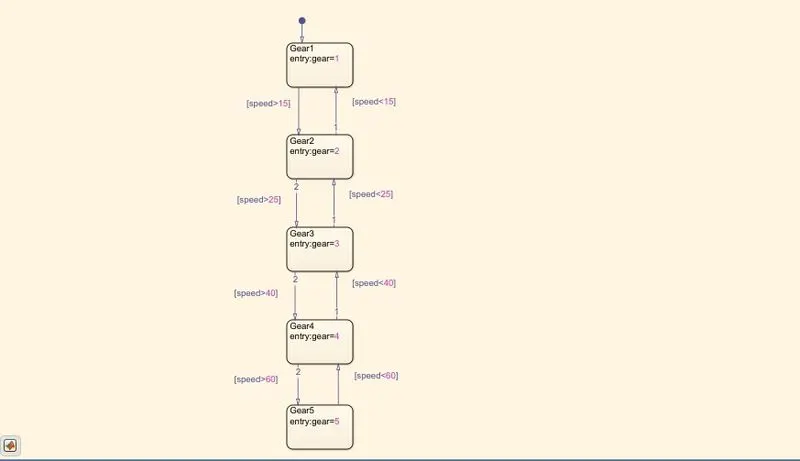
To create the Simulink chart for Gear shift based on the speed condition 0 to 15 means it's in first gear,16 to 25 means it's in second gear 26 to 40 means it's in third gear 41 to 60 means it is in fourth gear 61 or above means it's in 5th gear
Software Used
MATLAB R2020a
Body of the content: -
1)Washing Machine
The control logic of washing machine is to start the process of washing power supply of washing machine should be in on state, with an available water supply and then the cloth will keep 200sec for soaking after completion of that it will start washing it take 100 sec time after that it starts rinsing and will continue up to 20sec then it goes to the next stage that is drying it consumes 50sec time to complete the activity after completion of the drying process the indicator will glow to indicate process completed.
Simulink Model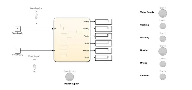
Inside the chart
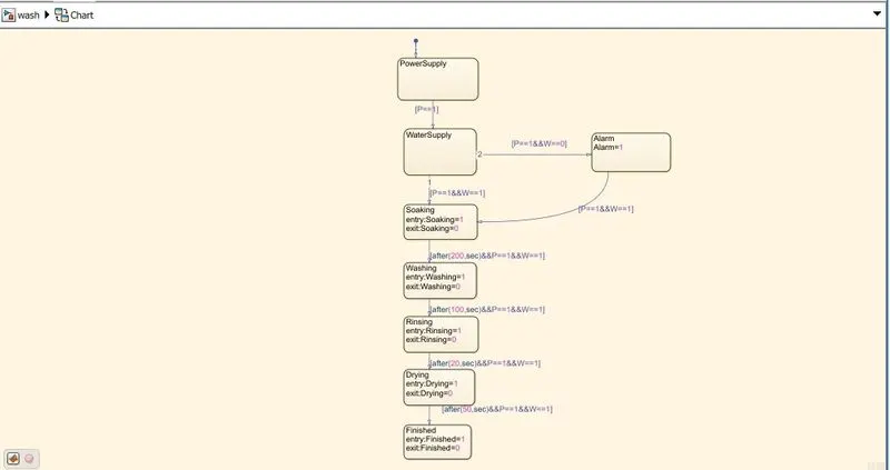
Blocks Used
Constant: -to Provide the constant value for power supply and water supply
Display: - to identify the value or condition of each stage of operation
Lamp: -To indicate the status of activity, power switch condition, washing machine activities like soaking, washing, rinsing, drying and the alarm condition such as no water, and to indicate washing completed
Toggle Switch:-it is used to Enable/Disable the power supply and to make available/Unavailable the Water supply
Chart:- it is used to create the conditions and the status of the wasting machine
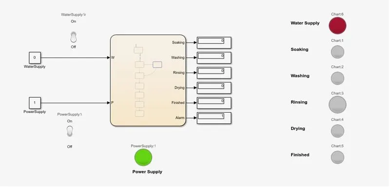
While running the washing machine at the initial condition power supply is enabled and water supply not available then the indicator in the model shows the red indication as shown
The condition is created by keeping the toggle switch off the water supply kept in off position.
Water not Available
Then we made the condition of water supply kept available by changing the toggle switch condition to on then the Simulink model start working and the washing machine’s soaking indicator turn to green
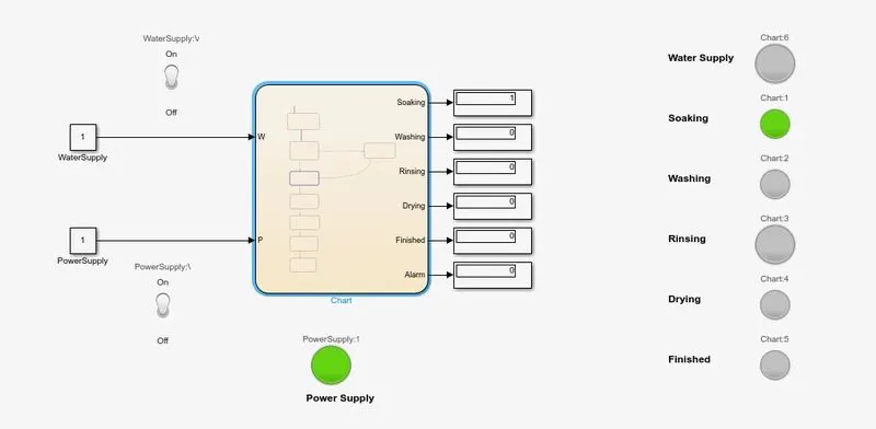
After the 200sec soaking, the washing machine moves to the next stage that is washing it washes the dress for 100sec during the time of washing it turn on the washing indicator
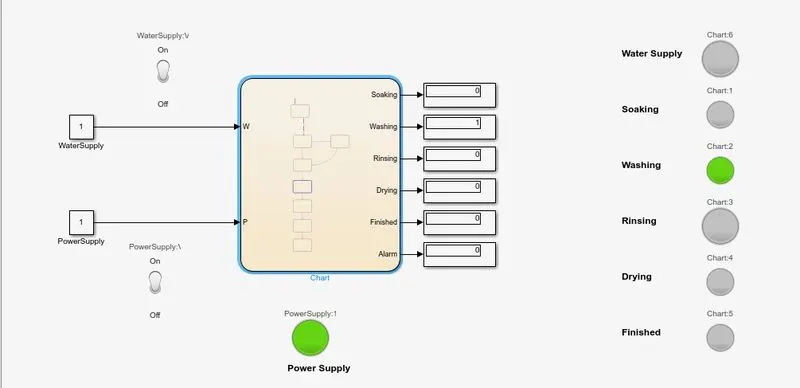
After completion of the washing process, it moves to the next stage such as rinsing it rinsing the cloths up to 20 sec
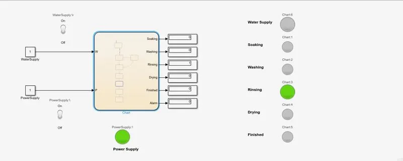
After completion of rinsing then the machine starts its drying process it takes 50sec time to complete the process
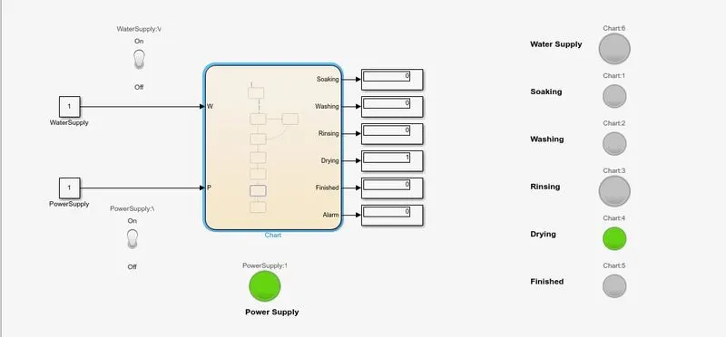
After the drying process, all process in the washing machine completed and will show the finished indicator
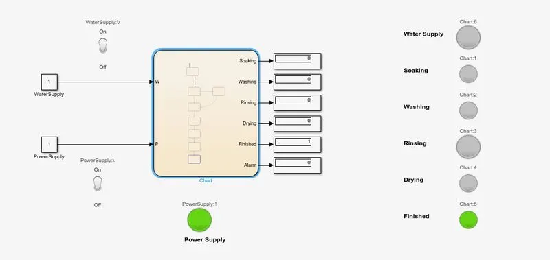
2)Automatic Gear System
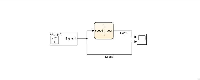
In the automatic gear system shifting is based on the speed in our 5gear system we gave the speed signal by using signal builder block and the gear position is confirmed by using the scope block the condition for gear shifting is created by Simulink chart system
Simulink model
Inside the chart
Blocks Used
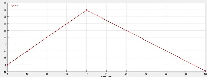
Signal builder: - It is used to create the speed input to the chart from the value 0 to 80 then return back to 0 here
Chart:-It is used to create the control logic of the gear system it is connected with input as speed and output as the gear number
Scope:- This block used to compare the speed and gear relation
The input signal from the signal builder is
The output signal received from the scope block based on the speed input
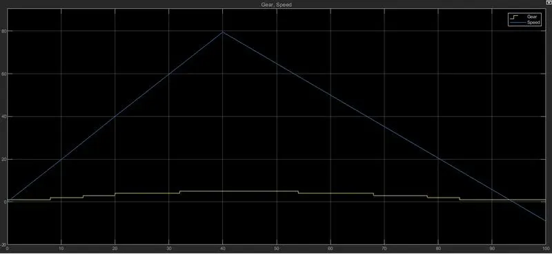
The output signal received (Gear only)to get a clear picture
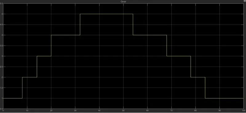
Here while giving the value of speed up to 15 it's running in the first gear after16 to 25 it moves to the second gear, at the 26 to the 40speed its gear shifts to its 3rd from 41 to 60 gear shifts to 4th, and finally from 61 onwards the gear shifts to 6th
conclusion
Hence the control logic of washing machine-implemented successfully with the indicators for water supply unavailability and completion of the process, and implemented based on the required time condition for the process of soaking, washing, rinsing, and drying and the Simulink chart model of automatic Gear system created and analyzed by varying the speed value